Eureka AIR delivers breakthrough ideas for toughest innovation challenges, trusted by R&D personnel around the world.

Fuel Cells Containing a Fuel Soluble in Aqueous Medium and Having a Boiling Point Higher Than 65'C

a fuel cell and aqueous medium technology, applied in the field of fuel, can solve the problems of methanol having major drawbacks for bulk use, less efficient but more manipulable, and difficult to limi

Inactive Publication Date: 2008-06-12
ARKEMA FRANCE SA
View PDF4 Cites 2 Cited by
  • Summary
  • Abstract
  • Description
  • Claims
  • Application Information

AI Technical Summary

Benefits of technology

The patent text discusses the use of methanol as a fuel in fuel cells and the challenges associated with its use, such as toxicity and the need for expensive membrane techniques. The technical problem addressed in the patent is finding substitutes for methanol and developing a cell that functions on ethanol or dimethyl ether. The text describes previous studies on potential methanol substitutes and their performance in fuel cells.

Problems solved by technology

However, the intricate problems associated with the storage of hydrogen have led to the search for solutions involving liquid fuels, which are possibly less efficient but more manipulable.
Although less efficient, they do not formally need to have methanol diluted in water and they can thus use fuels that are much more concentrated than in acid-mode cells.
However, methanol has major drawbacks for bulk use, due to its toxicity, but also on account of technological limitations with existing cells.
A technical limitation that will especially be mentioned is the problem of “crossover”, in which passage of methanol directly from the anode part to the cathode part, via the membrane, is observed in the cell.
This phenomenon associated with the permeability of the membrane to methanol is directly associated with the currently available membrane techniques, and appears to be difficult to limit with methanol.
Moreover, the physical characteristics of methanol can limit the conditions of use of the cell.
However, according to their study, a large amount of methanol is generated in the course of the reaction at the anode with the DMM and TMM cells.
DME is not a good product from the point of view of the performance of the cell, but might in practice be the best considering the toxicity factor of the degradation products at the anode.
However, besides the toxicity problem described previously, methanol has the drawback of having a low energy density and the vapour-reforming process is slow.

Method used


Image

  • Fuel Cells Containing a Fuel Soluble in Aqueous Medium and Having a Boiling Point Higher Than 65'C
  • Fuel Cells Containing a Fuel Soluble in Aqueous Medium and Having a Boiling Point Higher Than 65'C
  • Fuel Cells Containing a Fuel Soluble in Aqueous Medium and Having a Boiling Point Higher Than 65'C

Examples


examples

Polyoxymethylene Dialkyl Ethers

[0110]Examples of polyoxymethylene dialkyl ethers included in the composition of the fuels according to the invention are given in Table I below with their physical characteristics. This table also includes, for comparative purposes, molecules identified by an asterisk * that are not in accordance with the invention.

TABLE IBoilingFlashSolubilityMolarDynamicpointpointin water %massviscosityMolecule° C.Density° C.at 20° C.g · mol−1(cP)CH3—(OCH2)2—OCH31050.95971431106dioxymethylene dimethyl etherCH3—(OCH2)3—OCH31561.024228136trioxymethylene dimethyl etherCH3—(OCH2)4—OCH32021.0671166tetraoxymethylene dimethyl etherC2H5—(OCH2)—OC2H5880.83−56.331040.42 tooxymethylene diethyl ether25° C.C2H5—(OCH2)2—OC2H51400.91334134dioxymethylene diethyl etherC2H5—(OCH2)3—OC2H51850.974.5164trioxymethylene diethyl etheri-C3H7—(OCH2)—Oi-C3H7117-1190.81561.48132oxymethylene diisopropyl ethern-C4H9—(OCH2)—On-C4H91800.835460insoluble160oxymethylene dibutyl etherCH3OH *650.79112t...

examples 1 and 2

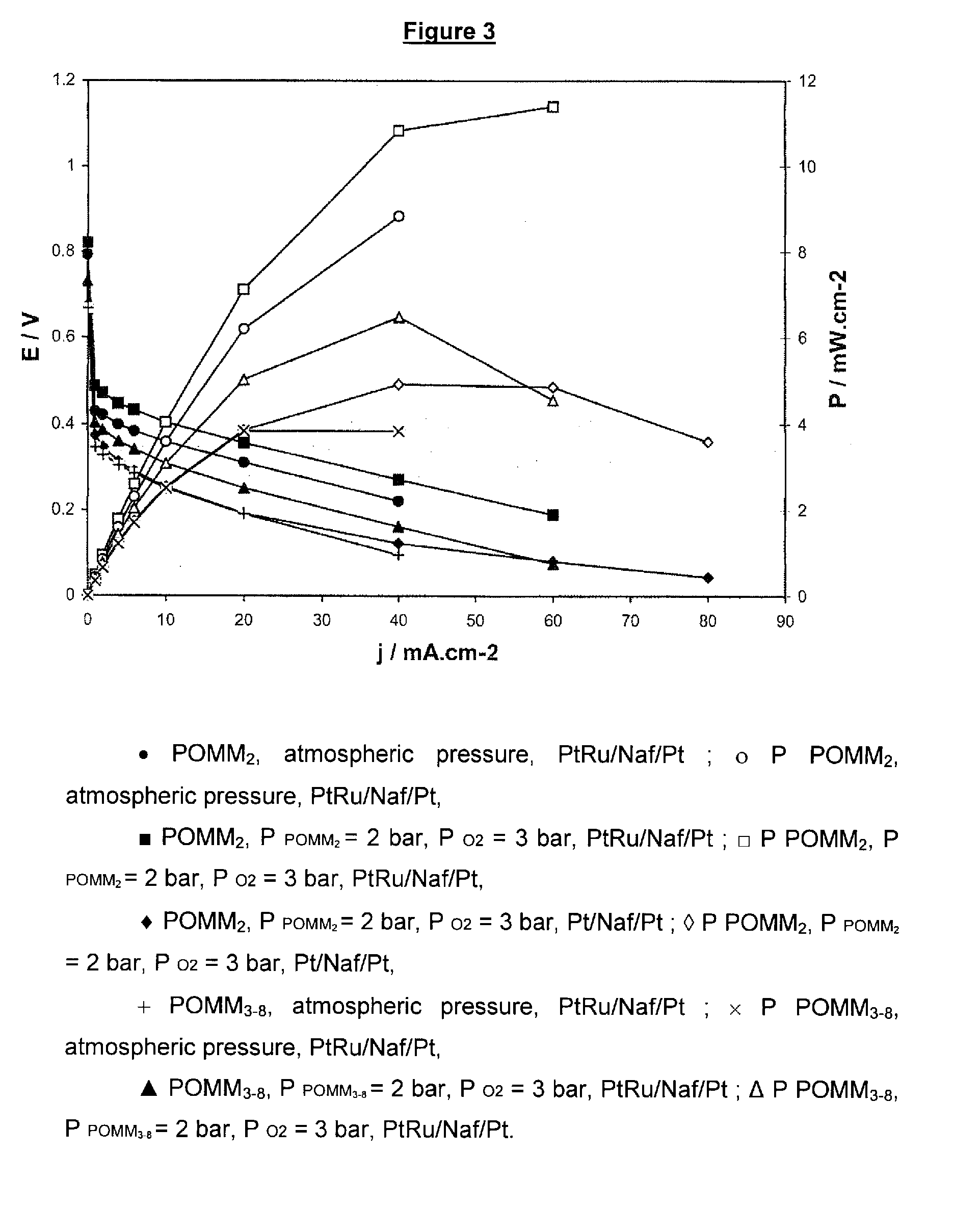
[0111]Two fuels according to the invention are used in Examples 1 and 2. The first is a POMM2 with a boiling point of 105° C., a molar mass of 106 g / mol and a mass per unit volume of 0.9597 g / ml. The second is a POMM3-8 with a distillation range of 153 to 268° C., a molar mass of 155.8 g / mol and a mass per unit volume of 1.064 g / ml.

[0112]These two fuels are obtained by reacting methylal with trioxane in the presence of an acidic resin, of the type such as Amberlyst® 15. The reaction medium is subjected to separation steps from which both POMM2 and POMM3-8 are obtained.

[0113]These fuels were tested in direct methanol fuel cells. Two series of tests were performed. In the first, a demonstration fuel cell of “H-TEC” type adapted for university teaching was used. The measurements of change of the voltages and current intensity and density were performed spotwise, i.e. without varying the operating conditions. The second series of tests was performed with a fuel cell of DMFC type operati...

example 1

[0118]The results obtained in Example 1 for the tests in acidic medium are summarized in Table 2 below.

TABLE 2E(mV)Iat(mA · cm−2)ElectrodesMembraneMediumI = 0at E = 0cathode: C—PtNafion H TEC10% MeOH4554.0anode: C—Ptwith Ni grille0.1 M H2SO4cathode: C—PtNafion H TEC10% POMM25255.3anode: C—Ptwith Ni grille0.1 M H2SO4cathode: C—PtNafion 11710% MeOH5952.5anode: C—Pt / Ruwith Ni grille0.1 M H2SO4cathode: C—PtNafion H TEC10% POMM27603.7anode: C—Pt / Ruwith Ni grille0.1 M H2SO4


PUM

PropertyMeasurementUnit
boiling pointaaaaaaaaaa
flash pointaaaaaaaaaa

Abstract

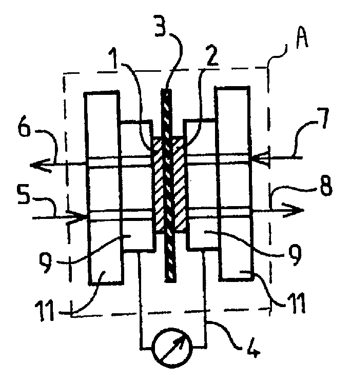
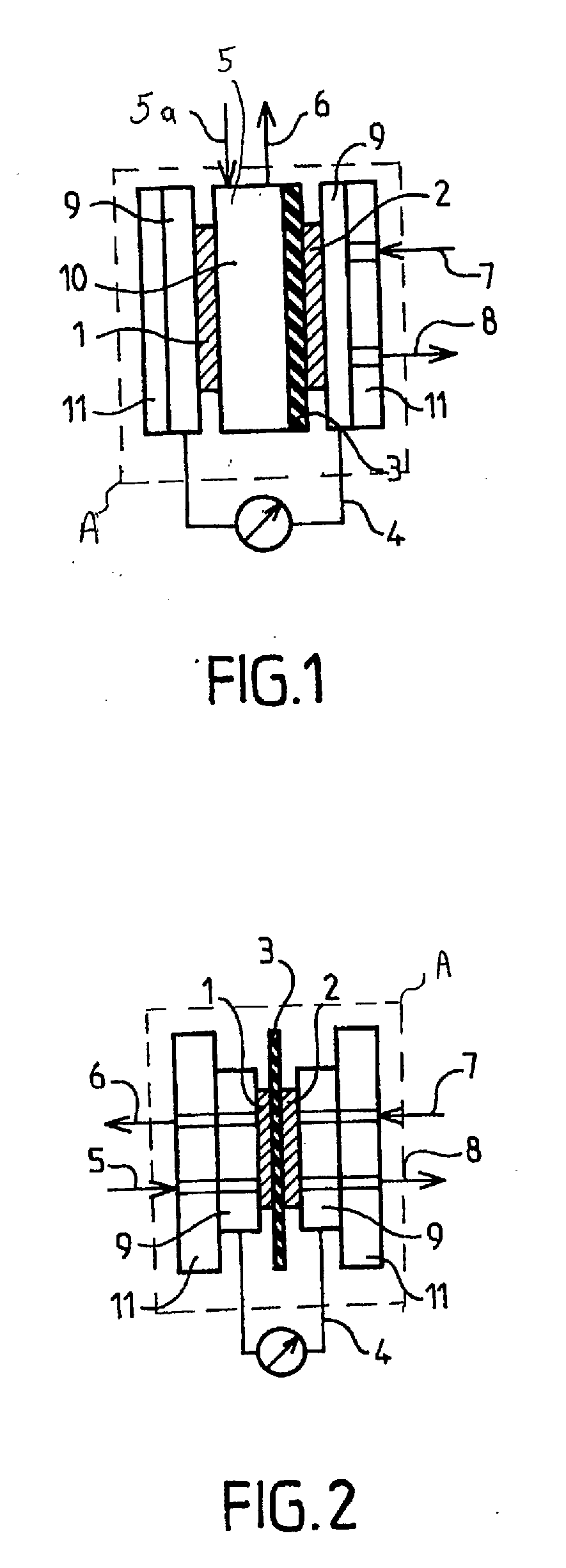
Fuel cell comprising a leaktight container (A) containing a catalytic anode (1) and a catalytic cathode (2) in contact with an electrolysable liquid medium (5), current collectors (9) connected, respectively, on the one hand to the anode and to the cathode, and on the other hand to an electrical circuit (4), characterized in that the liquid medium is an aqueous medium containing a fuel that is at least partially soluble in the aqueous medium, at the temperature of use of the cell, the said fuel having a boiling point of greater than 65° C.

Description

FIELD OF THE INVENTION[0001]Fuel cells are devices for converting the energy of a chemical reaction into electricity. Unlike batteries, the fuel and the oxidant are stored outside the cell. The fuel cell can thus produce energy as long as fuel and oxidant are supplied. The fuel cell produces an electromotive force by placing them in contact with two catalytic electrodes separated by or in contact with an electrolyte, which is usually in the form of a solid polymer that also acts as a barrier to the passage of gaseous reagents. The fuel is placed in contact with the anode, where it is dissociated to form ions, generally H+ or OH−, and electrons e−. The electrons pass into the conductive structure of the electrode (anode) and then circulate in the external electrical circuit of the system with production of energy. The ions pass through the electrolyte to the cathode. This cathode is fed with an oxidizing agent that forms at the surface, via electrochemical reduction, types of oxides ...

Claims


Application Information

Patent Timeline
Patent Type & Authority Applications(United States)
IPC IPC(8): H01M2/02H01M8/22
CPCH01M4/92H01M8/04082Y02E60/50Y02E60/523H01M8/22
Inventor DUBOIS, JEAN-LUC
Owner ARKEMA FRANCE SA
Why Eureka
Eureka Blog
Learn More