Method for Catalyst Coating of a Substrate

a substrate and substrate technology, applied in the direction of catalyst activation/preparation, metal/metal-oxide/metal-hydroxide catalysts, physical/chemical process catalysts, etc., can solve the problems of affecting engine performance and fuel consumption, overlap of coating compounds is particularly problematic for the automobile industry, and the thickness of the coating can be more precisely controlled , the effect of reducing the resistance to the flow of gases to be treated through the substra

Inactive Publication Date: 2008-06-19
BASF CATALYSTS LLC
View PDF15 Cites 36 Cited by
  • Summary
  • Abstract
  • Description
  • Claims
  • Application Information

AI Technical Summary

Benefits of technology

[0017]The present invention provides a system for applying a catalyst composition to an interior of a hollow substrate which eliminates the overlap or gap of the coating slurry. Generally stated, the system comprises coating a substrate with a catalyst composition by immersing the substrate into a vessel containing a bath of coating slurry and applying a vacuum to the partially immersed substrate at an intensity and time sufficient to draw the coating slurry upwardly from the bath into each of a plurality of channels located in the interior of the hollow substrate; removing the substrate from the bath; rotating the substrate 180°; and applying a blast of pressurized air to the substrate at an intensity and time sufficient to distribute the coating slurry within the channels of the substrate to form a uniform coating profile therein.
[0018]The term “uniform coating profile” as used herein means that each channel of the substrate will be coated over the same length. Advantageously, the present invention provides a system whereby the overlap or gap of the catalytic composition on the substrate is completely eliminated. This provides distinct advantages for catalytic converters. First, less precious metal may be used because the catalytic composition is evenly distributed throughout the substrate. Second, there is more precise control over the placement of the catalyst which is particularly advantageous when using multiple catalyst coating compositions. Third, by virtue of removing the overlap or gap, the thickness of the coating can be more precisely controlled, particularly in multi coating applications. Resistance to the flow of gases to be treated through the substrate is thereby reduced, resulting in better control over and less severe pressure drops through the channels. When such substrates are used as catalytic conve

Problems solved by technology

Such systems have been unsuccessful in providing a uniform coating thickness and a uniform coating profile wherein the catalyst coating is deposited over the same length of each of the channels.
Overlap of the coating compound is particularly problematic to the automobile industry.
The overlap area increases the delta pressure across the catalyst converter which adversely impacts engine performance and fuel consumption and increases the engine's wear.
Equa

Method used


Image

  • Method for Catalyst Coating of a Substrate
  • Method for Catalyst Coating of a Substrate
  • Method for Catalyst Coating of a Substrate

Examples


Embodiment Construction

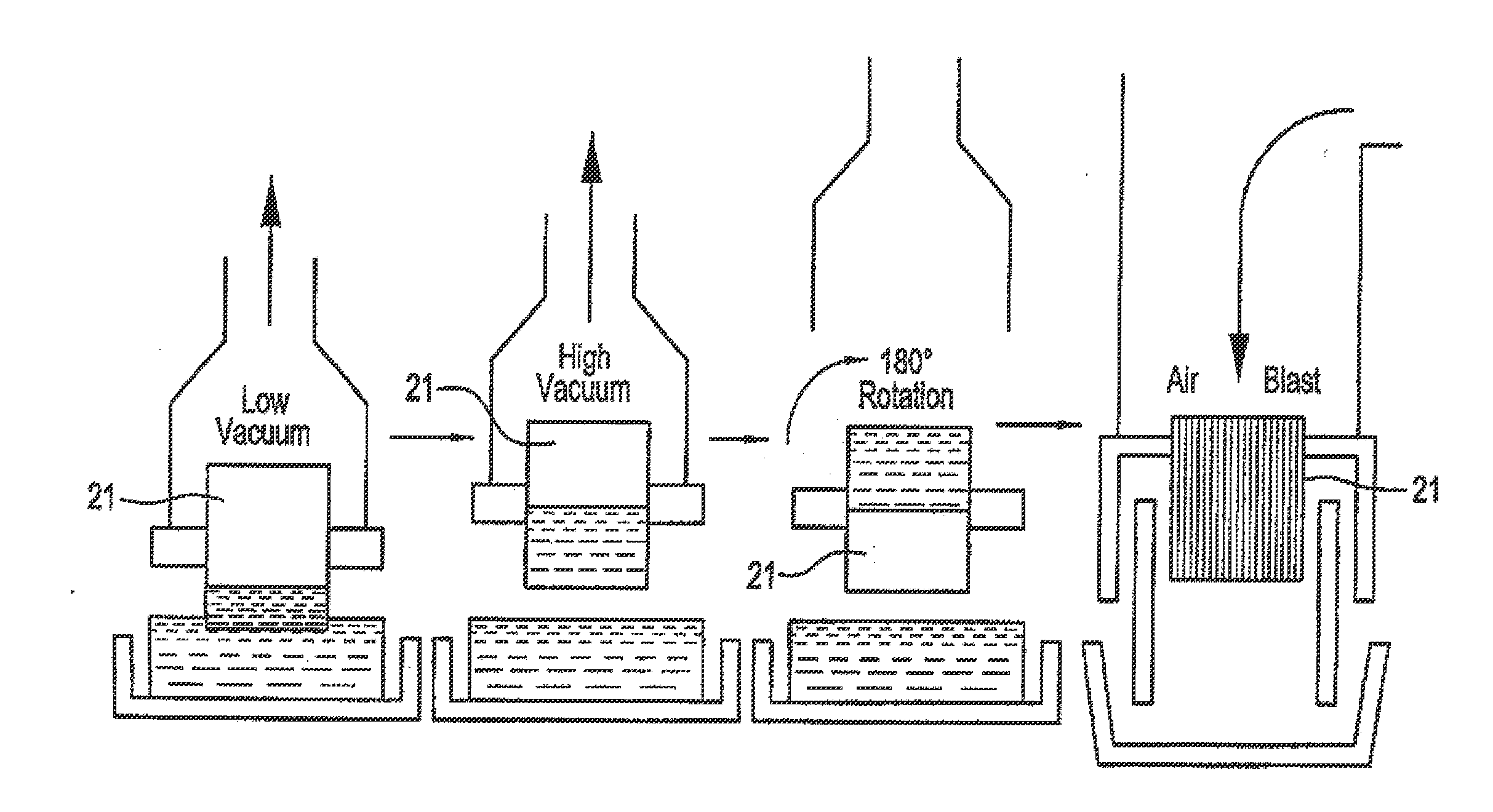
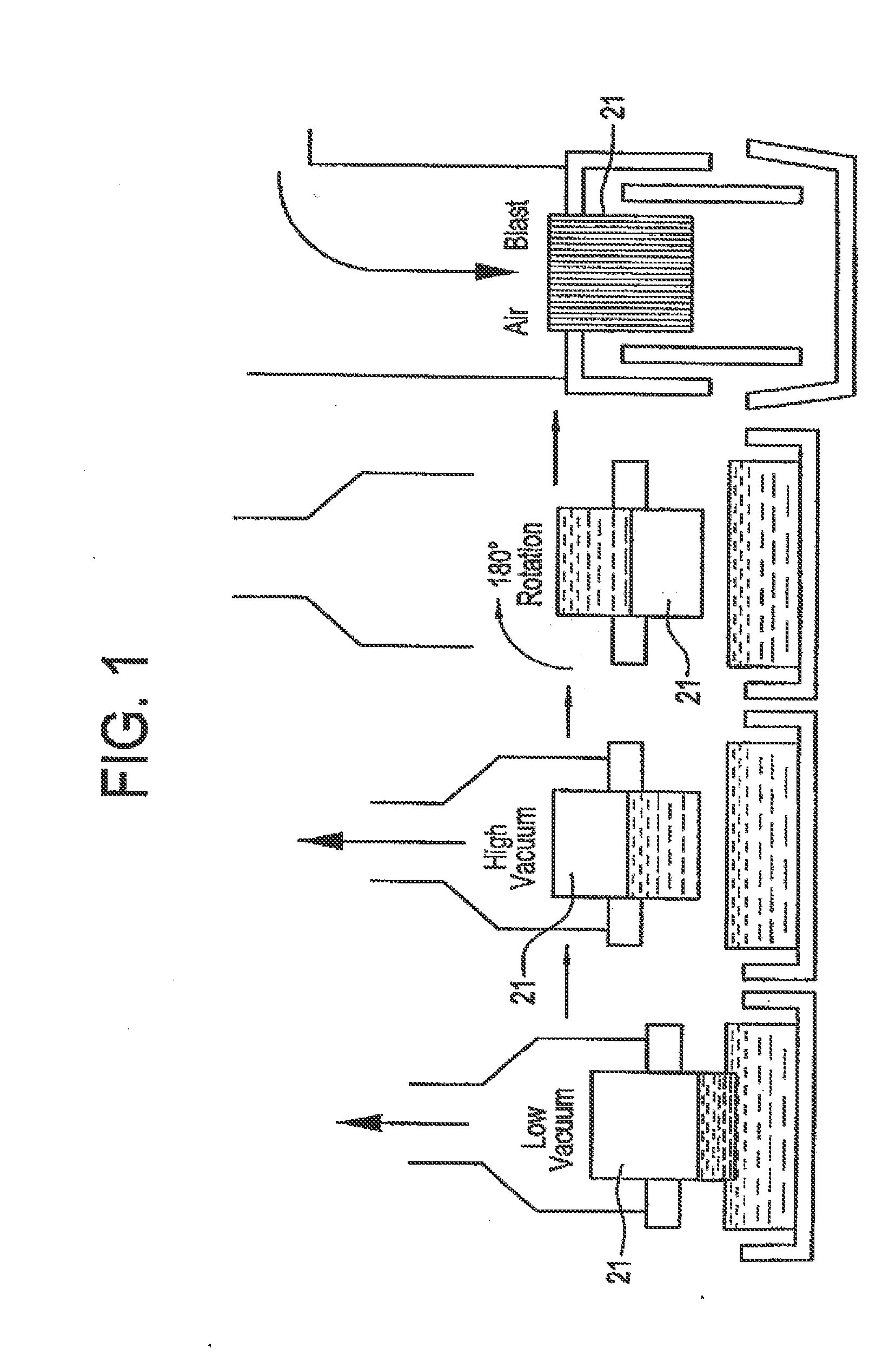
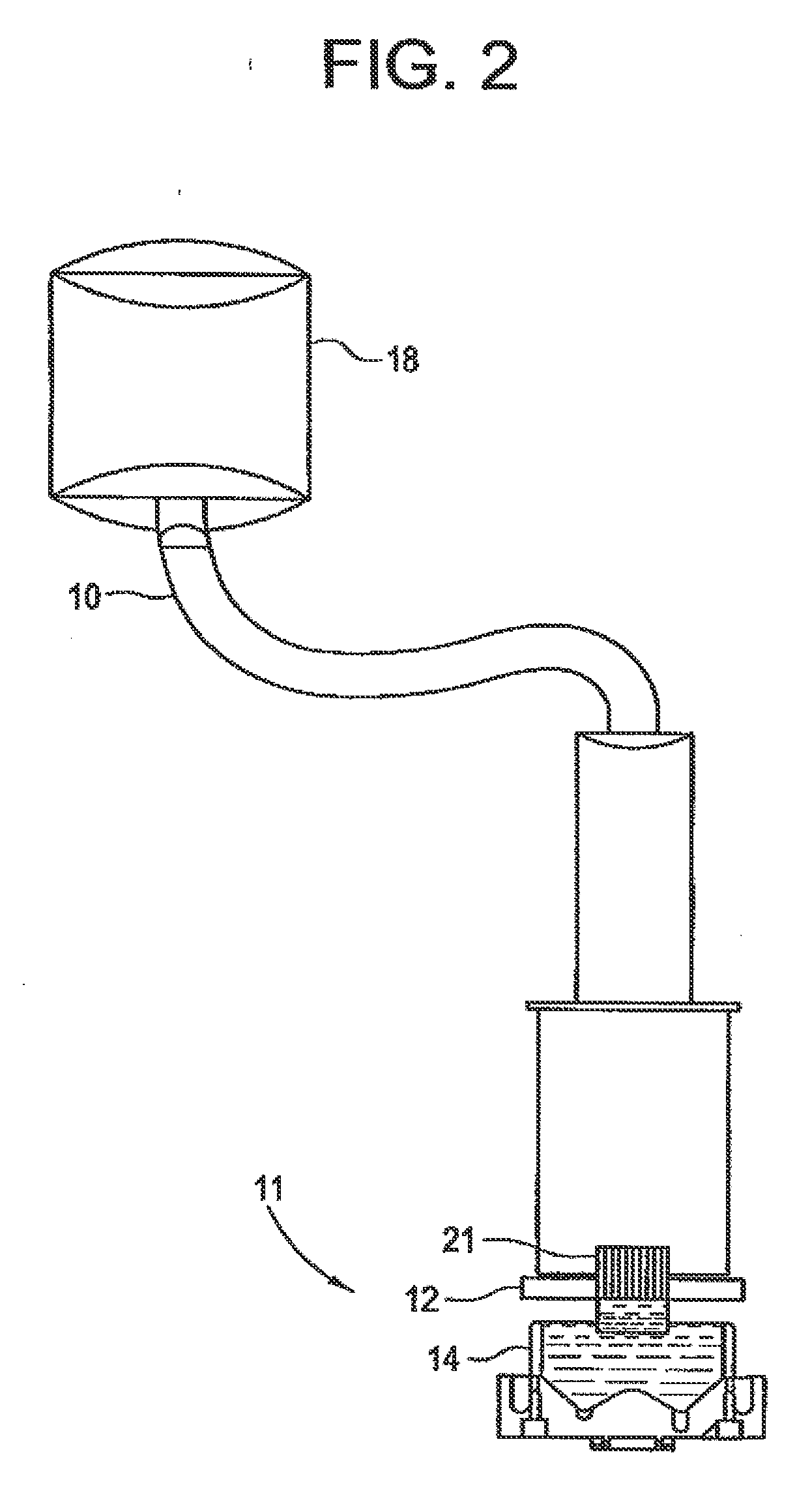
[0030]The present invention is directed to an improved system for coating a catalytic composition onto a substrate whereby the catalytic composition is uniformly coated within the interior surface of the substrate. The system of the present invention combines vacuum infusion coating with an air blast apparatus to provide a uniformly coated substrate without gaps or overlap of the catalytic composition within the interior of the substrate. As a consequence of the present invention, production output is increased and less precious metal is required in the catalytic composition, making a higher quality catalysts less expensive to produce. Moreover, automobiles using the catalysts of the present invention exhibit reduced fuel consumption, making these materials much more attractive to the automobile industry.

[0031]More specifically, the system of the present invention comprises coating a substrate with a catalyst composition by immersing the substrate into a vessel containing a bath of ...


PUM

PropertyMeasurementUnit
Fractionaaaaaaaaaa
Fractionaaaaaaaaaa
Pressureaaaaaaaaaa

Abstract

A catalyst composition is applied to an interior of a hollow substrate. The composition is coated on the substrate by immersing the substrate into a vessel containing a bath of coating slurry. A vacuum is then applied to the partially immersed substrate. The intensity of the vacuum and its application time is sufficient to draw the coating slurry upwardly from the bath into each of a plurality of channels located in the interior of the hollow substrate. After removing the substrate from the bath, it is rotated 180°. A blast of pressurized air is applied at an intensity and for a time sufficient to distribute the coating slurry within the channels of the substrate to form a uniform coating profile therein.

Description

CROSS-REFERENCE TO RELATED APPLICATION[0001]This application is a continuation of U.S. application Ser. No. 10 / 228,754, filed Aug. 27, 2002, the disclosure of which is hereby incorporated by reference in its entirety.FIELD OF THE INVENTION[0002]The present invention relates to an apparatus and method for coating a substrate, and more particularly to an apparatus and method for impregnating monolithic substrates with a catalytic material.BACKGROUND OF THE INVENTION[0003]Catalytic converters are well known for the removal and / or conversion of the harmful components of exhaust gases. Catalytic converters have a variety of constructions for this purpose. In one form the converter comprises the rigid skeletal monolithic substrate on which there is a catalytic coating. The monolith has a honeycomb-type structure which has a multiplicity of longitudinal channels, typically in parallel, to provide a catalytically coated body having a high surface area.[0004]The rigid, monolithic substrate c...

Claims


Application Information

Patent Timeline
IPC IPC(8): B05D5/00
CPCB05D1/002B05D1/18B05D3/042B01J37/0215B05D7/22B01J23/40B05D3/0493
Inventor ROSYNSKY, VICTORBLAMBLE, KENNETH W.BIBBEE, BRENT C.CORNELIUS, JERRY D.QUIGLEY, RALPH A.GRAMICCIONI, GARY A.FUNABIKI, MASAKIKAWAUCHI, TUNEHISATAKAHASHI, TOMOYA
Owner BASF CATALYSTS LLC
Why Eureka
Try Eureka