
Method for determining cylinder-specific combustion features of an internal combustion engine

a technology of internal combustion engine and combustion feature, which is applied in the direction of machines/engines, electric control, instruments, etc., can solve the problems of high additional cost of production use of cylinder-pressure sensors, very different combustion processes, and high cost of cylinder-pressure sensors, so as to achieve easy realization, more cost-effective effect, and effect on accuracy

Inactive Publication Date: 2008-06-26
ROBERT BOSCH GMBH
View PDF7 Cites 14 Cited by
  • Summary
  • Abstract
  • Description
  • Claims
  • Application Information

AI Technical Summary

Benefits of technology

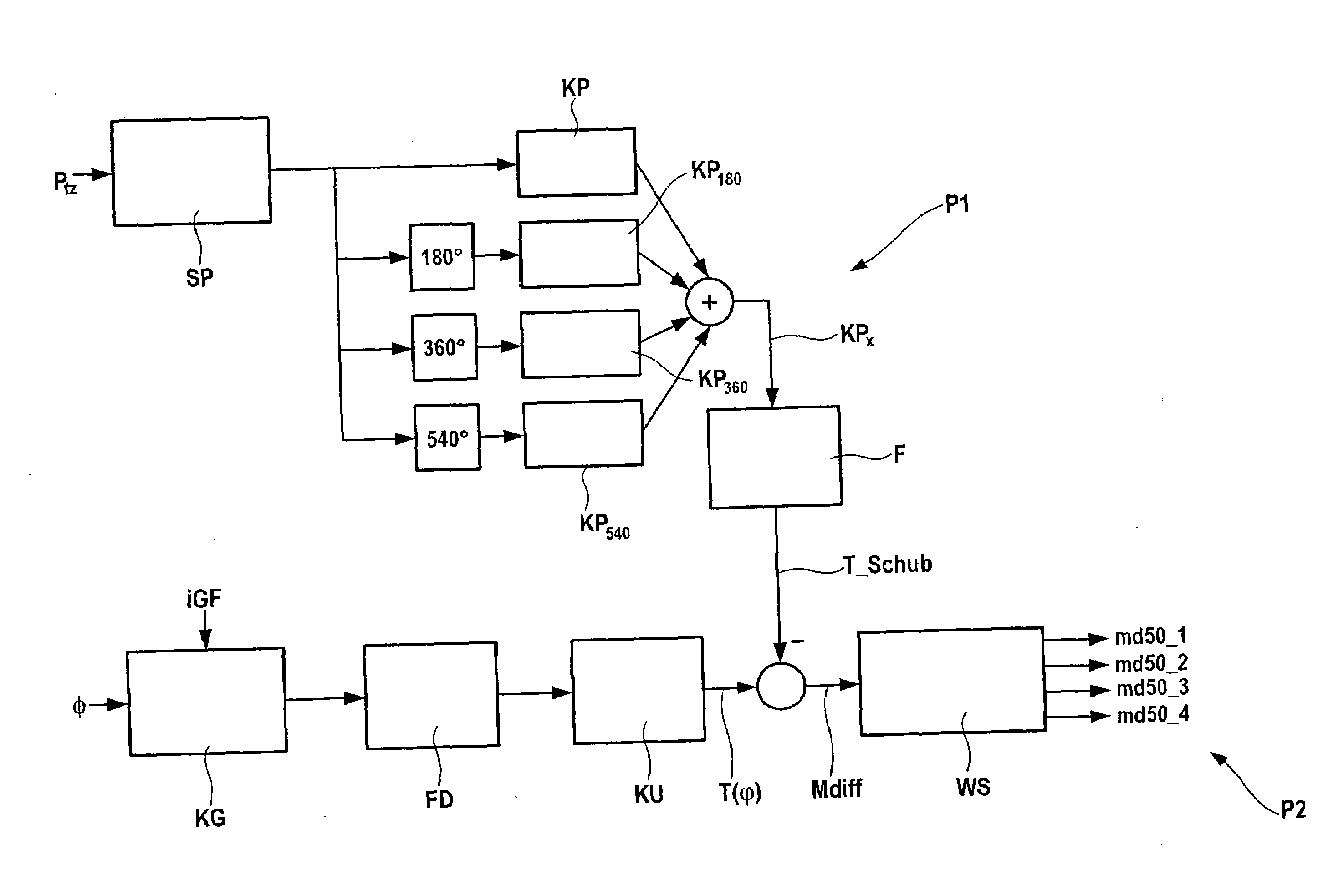
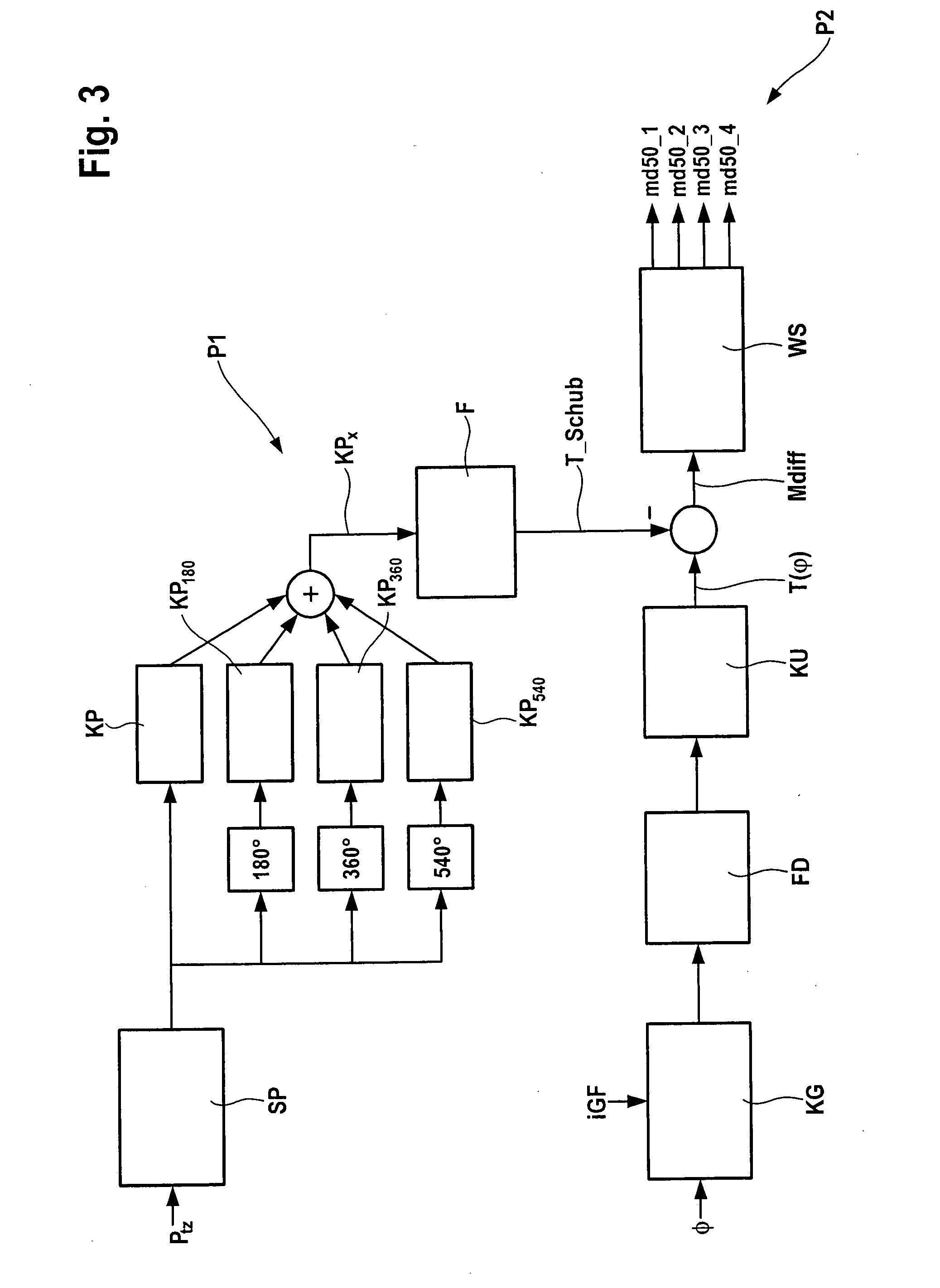
[0015]According to example embodiments of the present invention, a method is provided to obtain cylinder-specific features with respect to the combustion from a speed signal, and subsequently to use them for the closed-loop or optimized open-loop control of the combustion process. The speed signal is subject to various cross influences which must be eliminated first before information relevant to the combustion can be extracted from the signal curve. Thus, it is necessary to compensate for the influence of the dragged engine, taking into account the instantaneous charge-air pressure, the influence of the so-called oscillating masses (piston mass and proportional connecting-rod mass) and the influence of the crankshaft torsion. The compensation of these cross influences allows the calculation of a reconstructed gas-torque curve of the combustion (also known as differential torque curve), based on which, features regarding the combustion position as well as the mean indicated torque may be obtained.
[0017]In comparison to a full indication of cylinder pressure (i.e., a pressure sensor in each cylinder), the example method of the present invention having one indicated cylinder is more cost-effective because of the reduced number of pressure sensors (speed signal is available in any case) and is more easily realizable from a standpoint of design engineering.
[0018]The purely speed-based method for controlling the combustion position may be suitable for equalization of the cylinders. Here, the problem occurs that the absolute values of the combustion-position feature are strongly speed-dependent and load-dependent, and are significantly influenced by further cross influences such as errors in estimating the compression torque from an incorrectly measured charge-air pressure. In the example method of the present invention using a guide cylinder, the compression torque as well as the absolute value of the combustion position are advantageously determined based on the available combustion-chamber pressure signal, which has a significant effect on the accuracy. A further advantage of the example method is the possibility of compensating for various sensor errors like, for example, pulse-generating-wheel errors, with the help of the available pressure signal.

Problems solved by technology

For design reasons, already during steady-state operation, this leads to different filling compositions (ratio of inert gas / fresh air) specific to each cylinder, and as a result of manufacturing tolerances and aging effects of the engine over its service life, leads both to combustions proceeding very differently specific to each cylinder, and to sharp sample strews.
This, in turn, leads to very different pollutant and noise emissions specific to each cylinder, which is unwanted.
In principle, the combustion position can be determined robustly by cylinder-pressure indication; however, the additional costs for the production use of cylinder-pressure sensors are so high that, particularly in the case of smaller engines (e.g., 4 cylinder) and high piece numbers, they must be judged as critical.
Here, the problem occurs that the absolute values of the combustion-position feature are strongly speed-dependent and load-dependent, and are significantly influenced by further cross influences such as errors in estimating the compression torque from an incorrectly measured charge-air pressure.

Method used


Image

  • Method for determining cylinder-specific combustion features of an internal combustion engine
  • Method for determining cylinder-specific combustion features of an internal combustion engine
  • Method for determining cylinder-specific combustion features of an internal combustion engine

Examples


Embodiment Construction

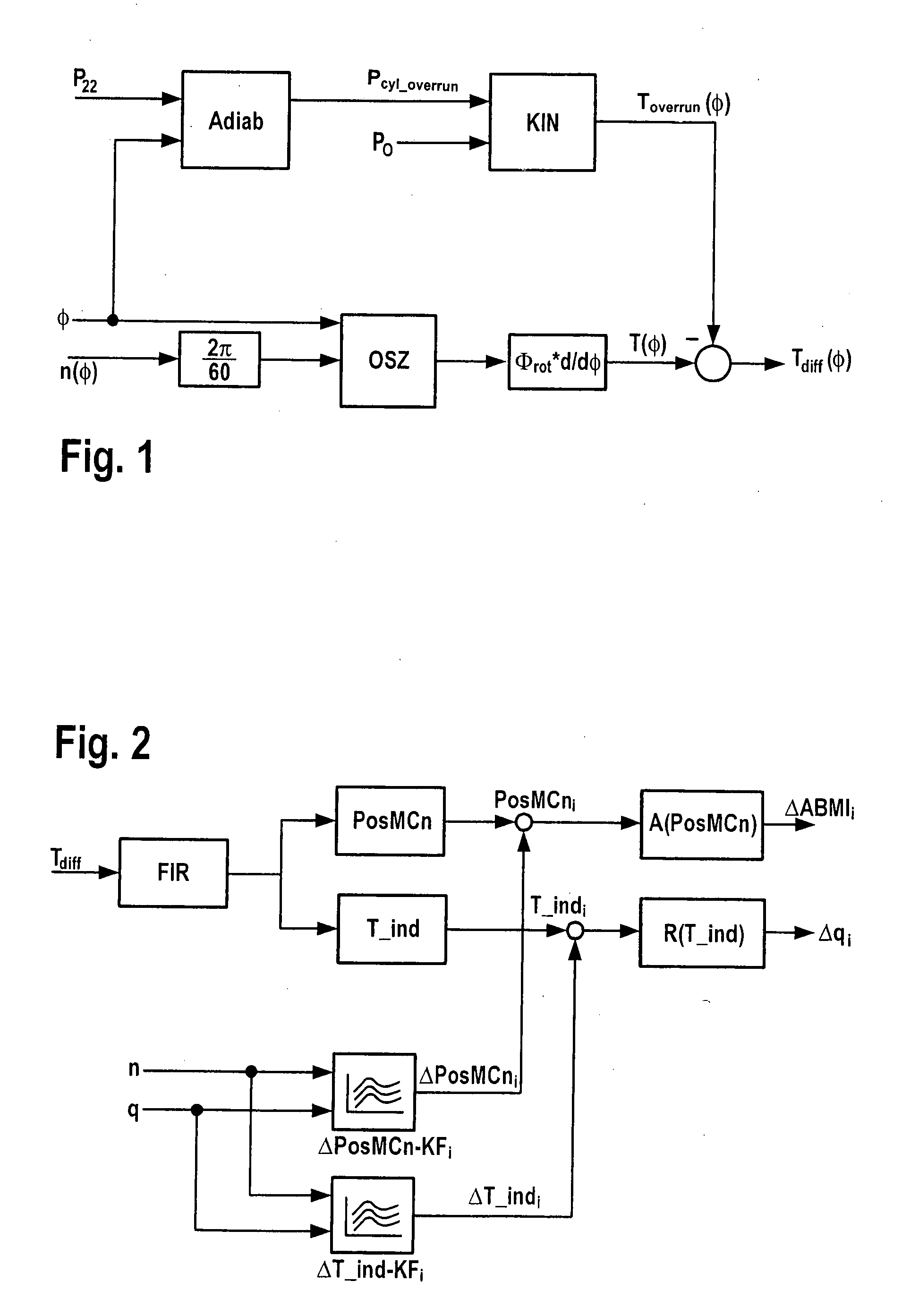
[0025]In the following, the ascertainment, according to an example embodiment of the present invention, of combustion position PosMCn and of mean indicated torque T_ind is first of all explained with reference to the block diagram of FIG. 1. Subsequently, an alternative specific embodiment of the method according to the present invention is described, should one of the cylinders having a cylinder pressure sensor be indicated. Finally, exemplary embodiments are described for the control or adaptation on the basis of the ascertained variables.

[0026]FIG. 1 describes the part of the method up to the determination of a differential gas-torque curve T_Diff(φ) corresponding to the combustion. In a module OSZ, angular speed φ is subjected to a non-linear transformation which compensates for the influence of the oscillating masses of the internal combustion engine. After differentiation of corrected angular speed φ and multiplication by total moment of rotational inertia Θrot of the cranksha...


PUM


Abstract

A method for determining cylinder-specific combustion features of an internal combustion engine, the cylinder-specific combustion features being ascertained from a variable which represents the crankshaft speed, especially being ascertained from a signal of a crankshaft sensor or camshaft sensor. The cylinder-specific combustion features include a combustion position of at least one cylinder and / or a torque of the crankshaft.

Description

FIELD OF THE INVENTION[0001]The present invention relates to a method, a device, an internal combustion engine and a computer program for determining cylinder-specific combustion features of an internal combustion engine.BACKGROUND INFORMATION[0002]Increasing demands (e.g., US07, Euro5) on modern diesel engines with respect to their emissions, in addition to requiring new systems for exhaust-gas treatment, also require the development of new combustion processes for reducing emissions within the engine. So-called (partial-) homogeneous combustion processes (also known as (p)HCCI processes) represent one potential possibility in this regard. One characteristic these processes share in common is a sharply increased exhaust-gas recirculation (EGR) rate compared to conventional combustion processes. For design reasons, already during steady-state operation, this leads to different filling compositions (ratio of inert gas / fresh air) specific to each cylinder, and as a result of manufactu...

Claims


Application Information

Patent Timeline
IPC IPC(8): G01M15/06F02D45/00
CPCF02D35/028F02D41/008F02D35/023F02D41/3035F02D2200/1004F02D41/009F02D41/1497F02D2200/1012
Inventor RAICHLE, FRANZSKALA, PETERRUPP, ANDREASFISCHER, WOLFGANGKESSLER, MICHAELYOUSSEF, MOHAMEDBREUNINGER, JOERGHAMEDOVIC, HARISLOEFFLER, AXEL
Owner ROBERT BOSCH GMBH
Learn More