
Method of detecting analyte-molecule interactions

a technology of analyte and interaction, applied in the field of methods for detecting interactions, can solve the problem of no reliable techniques for identifying biomolecules or biomolecules in cells

Inactive Publication Date: 2008-06-26
SOUTHERN ILLINOIS UNIVERSITY
View PDF12 Cites 24 Cited by
  • Summary
  • Abstract
  • Description
  • Claims
  • Application Information

AI Technical Summary

Benefits of technology

"This patent describes a method for detecting interactions between a biomolecule and an analyte. The method involves using a separation system with electrodes to create a pH gradient and manipulate the position of the biomolecule of interest. The system can also detect changes in the shape of the electric field to identify complexes between the analyte and biomolecule. The technical effect of this invention is a more efficient and accurate way to detect interactions between biomolecules and analytes, which can aid in the development of new treatments and diagnostic tools."

Problems solved by technology

While a variety of techniques have been developed to detect interactions between small molecules and individual biomolecules, there are no reliable techniques for identifying the biomolecule or biomolecules in a cell that interact with a small molecule of interest.

Method used


Image

  • Method of detecting analyte-molecule interactions
  • Method of detecting analyte-molecule interactions
  • Method of detecting analyte-molecule interactions

Examples


examples

[0055]The following examples illustrate various embodiments of the invention.

examples 1-5

Characterization of Dynamic Isoelectric Focusing Theory

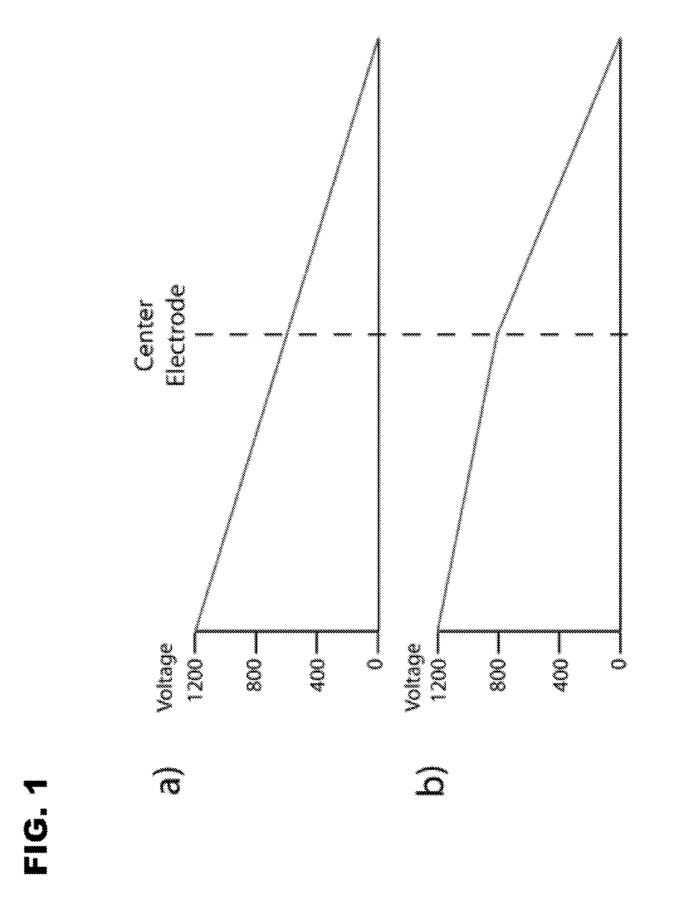
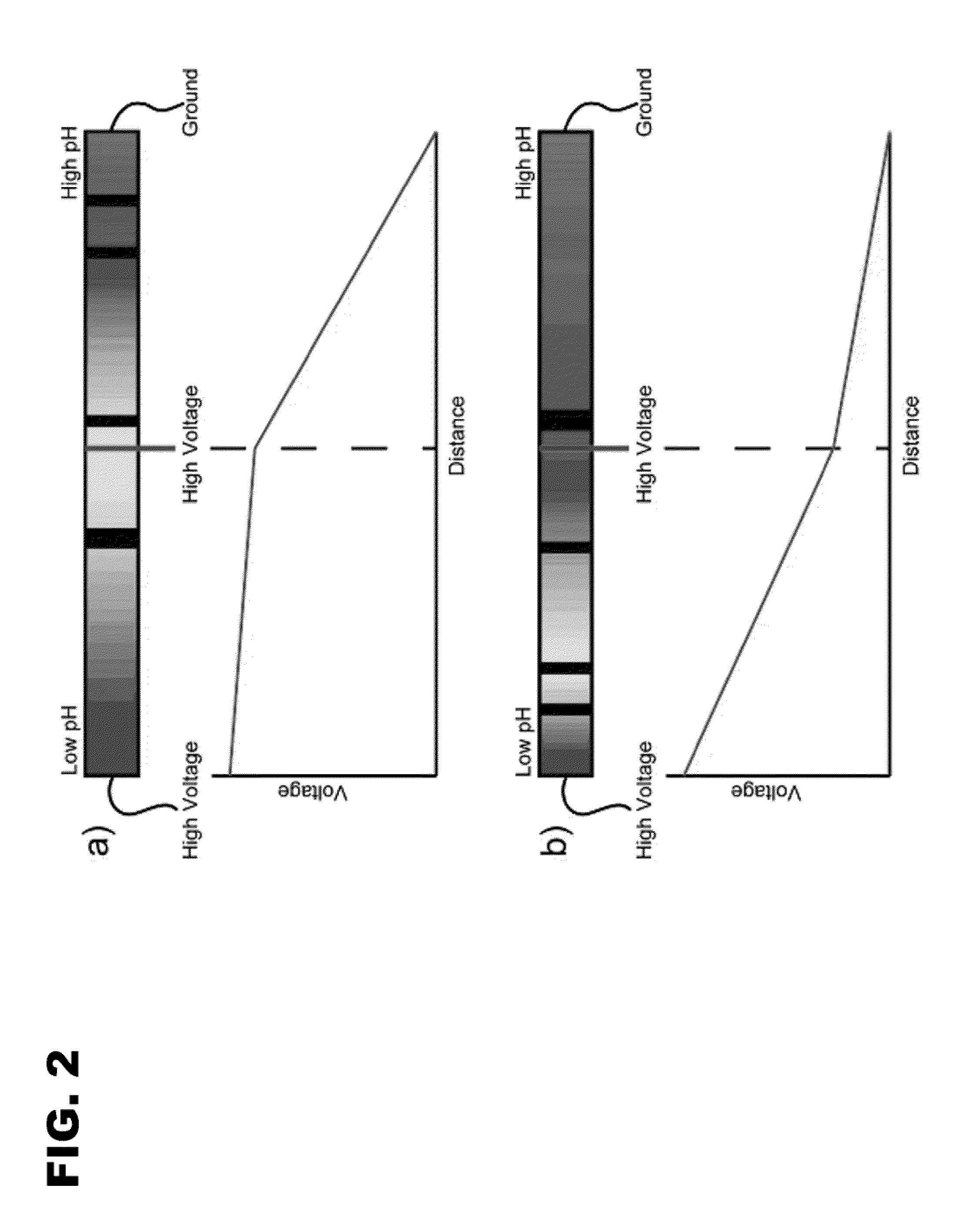
[0056]Dynamic isoelectric focusing (dynamic IEF) is similar to capillary isoelectric focusing (cIEF) in that it focuses proteins on the basis of their isoelectric point by establishing a pH gradient using ampholytes and an electric field. Although the pH gradient and the electric field in cIEF are constant, giving each focused protein in the sample a fixed position, dynamic IEF moves the pH gradient through manipulation of the electric field. This enables control over each protein's position and focused width. By changing the electric fields during a separation, focused proteins can be brought to a fixed sample point for collection and further analysis by chromatography or mass spectrometry, for instance. The dynamic control of each protein's position overcomes the major disadvantage of cIEF, which is the difficulty in interfacing to other techniques, while providing all of the advantages of cIEF.

[0057]Dynamic IEF establishes a ...

example 1

Proof-of-Concept with PTFE Tubing

[0070]Proof-of-concept tests were performed using PTFE tubing with an i.d., of 0.02 (˜528 μm) in a three-electrode configuration. The tubes were filled with universal indicator and a 3% ampholyte solution. Photographs of this setup are seen in FIG. 4. The relatively large tubing has several disadvantages, such as excess heating, siphoning, and eddy currents, but the size made it possible to easily see the pH gradients as they formed and were then moved. The anode contained 0.2 M acetic acid; the cathode, 0.5% ammonium hydroxide; and the center vial, 3% ampholyte. FIG. 4a shows the initial focusing conditions with voltages of 2200, 2195, and 0 V. As expected, the pH gradient forms between the center electrode and ground, and the high voltage section is completely acidic. The center voltage was then dropped to 1100 V, and the gradient was moved so that a neutral pH was present in the center, as shown in FIG. 4b. The refocusing took ˜10 min. Although th...


PUM

PropertyMeasurementUnit
voltageaaaaaaaaaa
voltageaaaaaaaaaa
voltageaaaaaaaaaa

Abstract

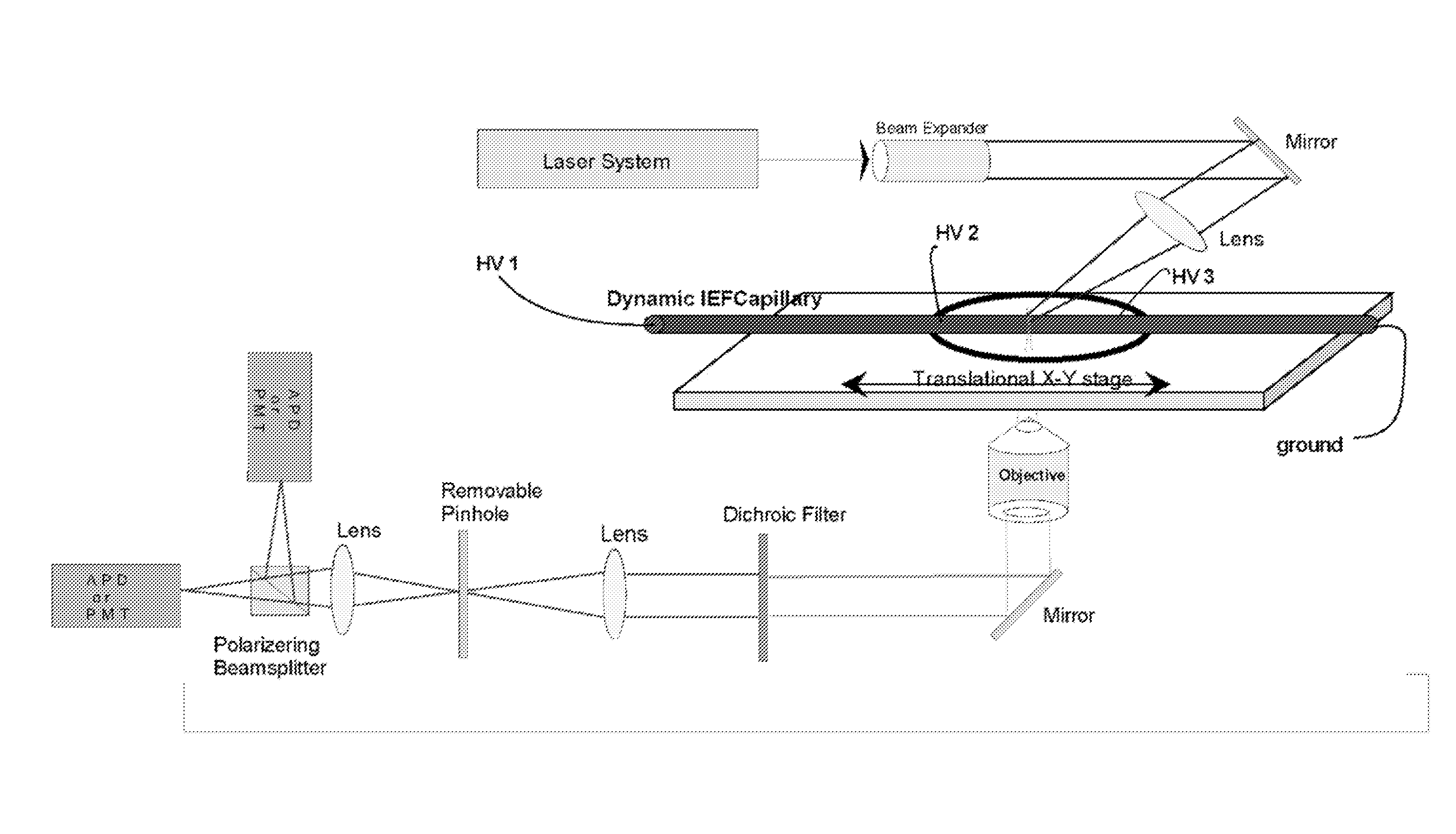
The invention provides methods for detecting an interaction between an analyte and a biomolecule. The method comprises separating at least one biomolecule according to its isoelectric point in the presence of a given analyte and detecting an interaction between the analyte and a biomolecule using fluorescence anisotropy. The method may further comprise collecting the analyte-biomolecule complex and analyzing the biomolecule.

Description

CROSS-REFERENCE TO RELATED APPLICATION[0001]This application claims priority to U.S. Provisional Application Ser. No. 60 / 862,814 filed on Oct. 25, 2006, which is hereby incorporated by reference in its entirety.GOVERNMENTAL RIGHTS[0002]This invention was made with Government support under grant number 1 R21 CA120691-01 awarded by the National Institutes of Health. The Government has certain rights in this invention.FIELD OF THE INVENTION[0003]This invention generally relates to methods for detecting an interaction between an analyte and a biomolecule using dynamic isoelectric focusing techniques and fluorescence anisotropy.BACKGROUND OF THE INVENTION[0004]Interactions between small molecules (or analytes) and proteins or other biomolecules in a cell are fundamental to biology and medicine. For example, many cells communicate with each other via small molecules that interact with cell membrane receptors. Oftentimes, a pharmaceutical compound is administered to a patient because it ha...

Claims


Application Information

Patent Timeline
Patent Type & Authority Applications(United States)
IPC IPC(8): B01D57/02C12Q1/08
CPCG01N33/561G01N27/44795
Inventor TOLLEY, LUKEMCCARROLL, MATT
Owner SOUTHERN ILLINOIS UNIVERSITY
Learn More