Coil Device and Nuclear Magnetic Resonance Imaging Apparatus Using the Same

a nuclear magnetic resonance imaging and coil technology, applied in the direction of measuring devices, magnetic measurements, instruments, etc., can solve the problems of increasing the complexity of circuit tuning, the uniformity of effective sensitivity declines, and the difficulty of application to large coils, so as to achieve uniform sensitivity. the effect of the rang

Inactive Publication Date: 2008-06-26
HITACHI LTD
View PDF12 Cites 12 Cited by
  • Summary
  • Abstract
  • Description
  • Claims
  • Application Information

AI Technical Summary

Benefits of technology

[0036]The present invention provides a coil device, which, with one coil, has a uniform sensitivity range and can be tuned with two different frequencies. It can be configured that one of the two tuning frequencies has a tuning mode of multiple patch resonator type, while the other has a tuning mode of bird cage type. Because of the characteristics of the tuning mode of multiple patch resonator type, the coil device of the present invention is applicable to the high-magnetic field MRI apparatus.
[0037]In the coil device of the present invention the space between first coils disposed adjacently is electromagnetically transparent, allowing the invasion into the RF electromagnetic field from outside. Consequently, the coil device of the present invention can be used in combination with other transmission coils disposed in the outside of the same. For example, in the application to the MRI apparatus, it is possible to use the coil device of the present invention exclusively as a receive only coil by using other larger coil placed outside for the RF transmission.
[0038]Further, according to the present invention, an MRI apparatus which is configured relatively simply by using the aforementioned coil device of the present invention as an RF coil and has homogenous sensitivity at two frequencies can be constructed.

Problems solved by technology

However, the method according to the Patent Document 1 has a disadvantage that since every other rung of those disposed in the circumferential direction is allocated to different frequencies, the uniformity of effective sensitivity declines.
The method described in the Patent Document 2 has disadvantages, which include increased complexity of tuning of circuits and difficulty of application to large coils for imaging the body trunk or the like in the high-magnetic field MRI at least 3 Tesla due to too small capacity of condensers.
The method described in the Patent Document 3 has such disadvantage that since the end of the bird cage coil is made of plural sets of endrings, the size in the vertical direction becomes too big and reduce the part for the shoulder when the human head is disposed inside the coil.

Method used


Image

  • Coil Device and Nuclear Magnetic Resonance Imaging Apparatus Using the Same
  • Coil Device and Nuclear Magnetic Resonance Imaging Apparatus Using the Same
  • Coil Device and Nuclear Magnetic Resonance Imaging Apparatus Using the Same

Examples


example 1

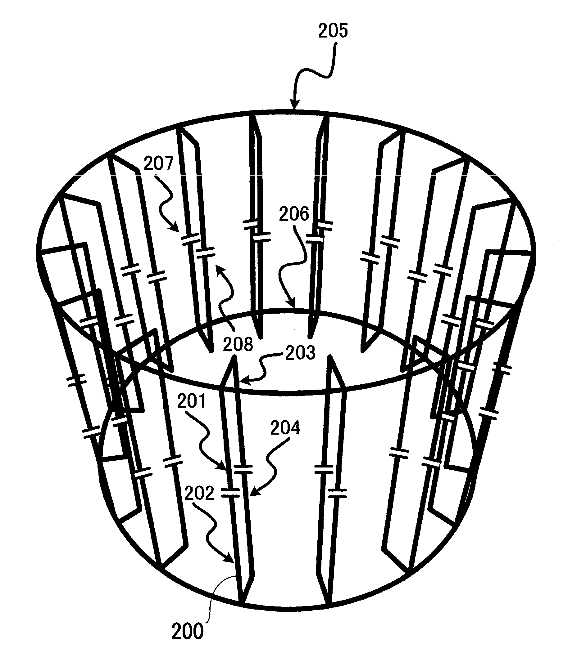
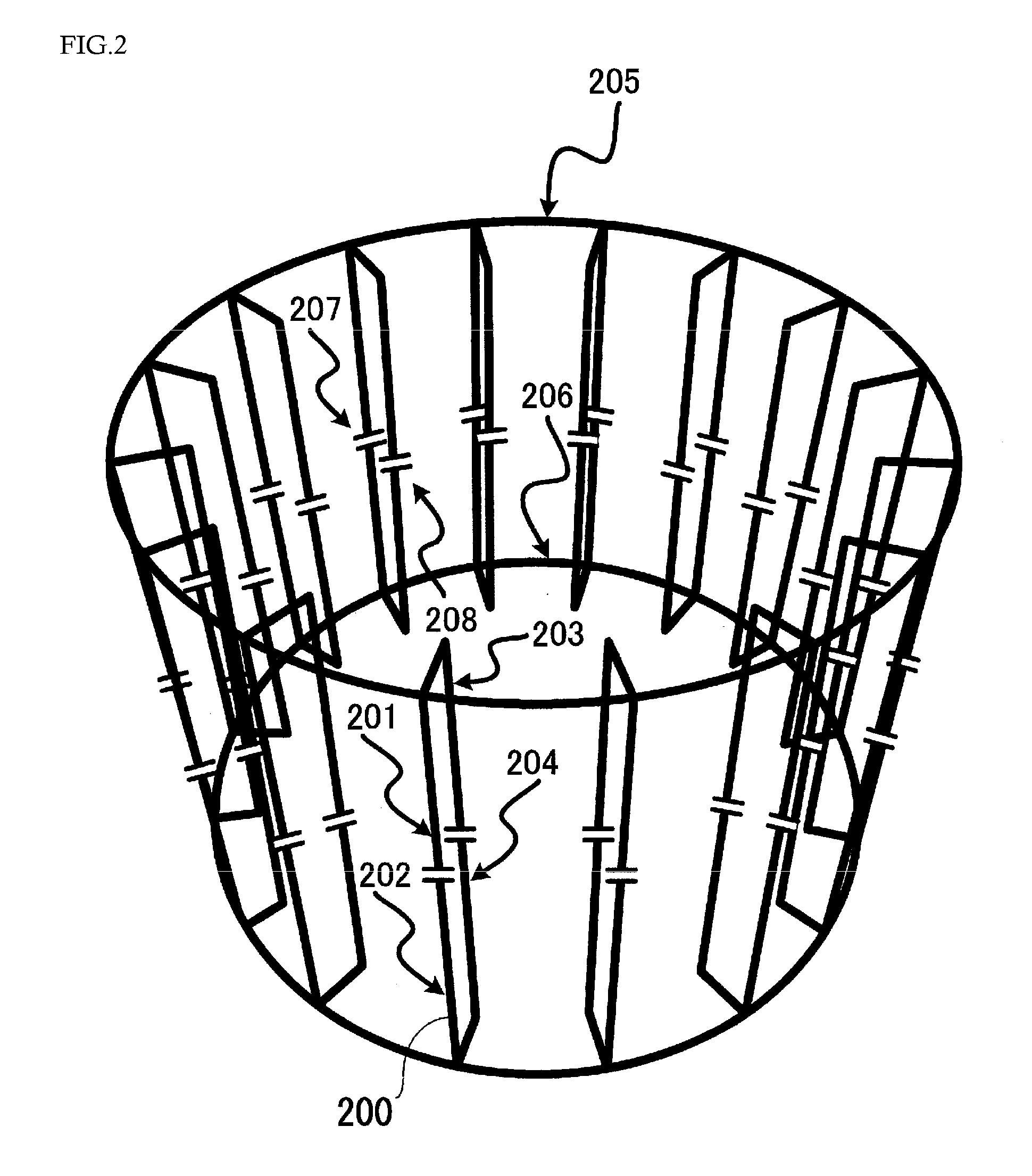
[0085]An example, in which the RF coil made of 16 first coils and second coils, as shown in FIG. 2, are installed in the MRI apparatus with the magnetic field strength of 3 Tesla to obtain hydrogen and carbon signals, will be explained.

[0086]In the present example, the coil was designed to have an axial length of 220 millimeter, outer diameter of about 334 millimeter and internal diameter of approximately 276 millimeter. Also, the value, C1, of the first condenser 207 sandwiched between the first conducting sections of the first coil was set at 17 pF, and the value, C2, of the condenser 208 between second conducting sections was set at 12 pF. Since the use of a copper rod of 4 millimeter in radius is assumed, the electric conductivity of copper was used.

[0087]Resonance characteristics of this RF coil obtained by simulation are shown in FIG. 8, where the horizontal and vertical axes represent the frequency and the impedance, respectively. The impedance was obtained by simulating the ...

example 2

[0097]This example explains concrete configuration of dual-frequency tuning coil which can be tuned with the frequencies of hydrogen and phosphor in the 3-Tesla MRI apparatus as in Example 1.

[0098]The RF coil of this example is, as in Example 1, the RF coil in the shape shown in FIG. 2. However, it is different from Example 1 in that the condenser 301 is inserted into the ring-shaped part of the second coil and its value was set at 250 pF. As mentioned earlier, by inserting the condenser into the ring-shaped part of the second coil, the tuning frequency of bird cage type can be raised. The simulation of resonance characteristics of the RF coil of this example revealed that the addition of the condenser 301 of 250 pF into the ring-shaped part of the RF coil in Example 1 could alter the bird cage type tuning frequency from 32 MHz to 52 MHz while maintaining the multiple patch resonator type tuning frequency at 129 MHz. The frequency of 52 MHz is almost identical with the tuning freque...

example 3

[0099]Resonance characteristics of the RF coil, in which two conducting parts of the first conducting section connected via the condenser 207 are connected with one conductor into one conductor without using the condenser 207 in Example 2, was examined. Other elements of the configuration were same with those of Example 2. Feeding was performed in parallel with the condenser 208 or 301 among the multiple number of condensers.

[0100]Simulation of the RF coil of this Example show that the bird cage type resonance mode appears, like the RF coil in examples 1 and 2, at the lower frequency range than that of the multiple patch resonator type resonance mode, and that the bird cage mode of high pass type appeared instead of the bird cage mode of low pass type in Example 1.

[0101]It was found that if the value C2 of the condenser 208 inserted into the second conducting section (inside the rung) is set at 5.8 pF, and the value of the condenser 301 of the second coil (ring part) at 119.7 pF, a ...


PUM


Abstract

An RF coil which is resonant and tuned with two different frequencies, has uniform space sensitivity and occupies less space is provided. The coil is, particularly suited to the high magnetic field MRI apparatus. The coil device is equipped with the multiple number of first coils 200 having the first conducting sections 201 and 202 and the second conducting sections 203 and 204, and the second coils 205 and 206 electrically connected with the end of the multiple number of first coils. In the first conducting sections, two conducting parts 201 and 202 are electrically connected via the first condenser 207, while in the second conducting sections, two conducting parts 203 and 204 are electrically connected via the second condenser 208. And the feeding circuit and/or receiving circuit are connected in parallel with the first condenser at one or two positions. By adjusting the capacity of the first and the second condenser, the RF coil having a uniform sensitivity range at two different frequencies can be configured.

Description

[0001]The present application claims priority from Japanese application JP 2006-304009 filed on Nov. 9, 2006, the content of which is hereby incorporated by reference into this application.TECHNICAL FIELD[0002]The present invention relates to a coil device to be used for the transmission and reception of electromagnetic waves and a nuclear magnetic resonance imaging apparatus (hereinafter called MRI apparatus) using the same.BACKGROUND ART[0003]In the MRI apparatus, imaging of a subject to be examined is performed by placing the subject in a uniform static magnetic field generated by magnets, irradiating electromagnetic fields to excite nuclear spins inside the subject body, and then by receiving nuclear magnetic resonance signals that are the electromagnetic field generated by the nuclear spins. The irradiation of electromagnetic waves and the reception of nuclear magnetic resonance signals are conducted by the RF coil which transmits or receives electromagnetic waves of radio freq...

Claims


Application Information

Patent Timeline
Patent Type & Authority Applications(United States)
IPC IPC(8): G01R33/34
CPCG01R33/3635G01R33/34046
Inventor HABARA, HIDETABITO, YOSHITAKASOUTOME, YOSHIHISAOCHI, HISAAKI
Owner HITACHI LTD
Why Eureka
Try Eureka