Clock supplying apparatus

a clock supply and clock technology, applied in the direction of generating/distributing signals, baseband system details, pulse techniques, etc., can solve the problems of increasing the number of man-hours for design and cost, increasing the mounting area, and difficult to reduce crosstalk noise generated, etc., to achieve high jitter reduction effect and simple configuration

Inactive Publication Date: 2008-06-26
SONY CORP
View PDF1 Cites 27 Cited by
  • Summary
  • Abstract
  • Description
  • Claims
  • Application Information

AI Technical Summary

Benefits of technology

[0028]A jitter reduction effect can be obtained by the mechanism just described.
[0029]With the clock supplying apparatu

Problems solved by technology

However, the countermeasures against power supply noise for a clock generation circuit described hereinabove are disadvantageous in that they increase the number of man-hours for design and the cost.
Meanwhile, the method of laying a clock transmission line in a spaced relationship from other signal lines or shielding a clock transmission line on the opposite sides with a GND signal line as a countermeasure against crosstalk

Method used


Image

  • Clock supplying apparatus
  • Clock supplying apparatus
  • Clock supplying apparatus

Examples


first embodiment

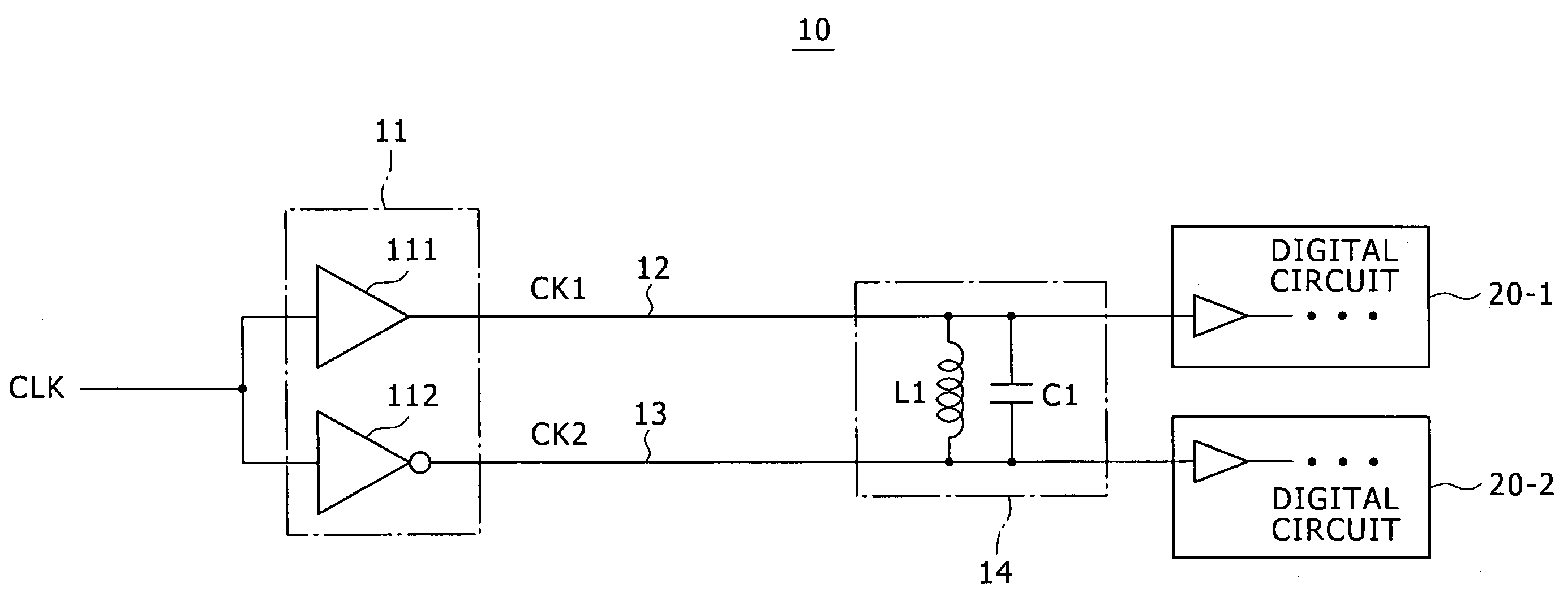
[0044]FIG. 1 shows an example of a configuration of a stabilized clock supplying apparatus to which the present invention is applied.

[0045]Referring to FIG. 1, the stabilized clock supplying apparatus 10 shown includes, as principal components thereof, a differential clock driver section 11, a first clock line 12, a second clock line 13, a parallel resonance circuit 14 of an inductor L1 and a capacitor C1, and a pair of digital circuits 20-1 and 20-2.

[0046]The differential clock driver section 11 includes a first clock driver 111 and a second clock driver 112. The first clock driver 111 performs waveform shaping or the like for an original clock CLK of a predetermined frequency inputted thereto to generate a first clock CK1 of a positive phase and supplies the first clock CK1 through the first clock line 12. The second clock driver 112 performs waveform shaping or the like for the original clock CLK of the predetermined frequency inputted thereto to generate a second clock CK2 of a ...

second embodiment

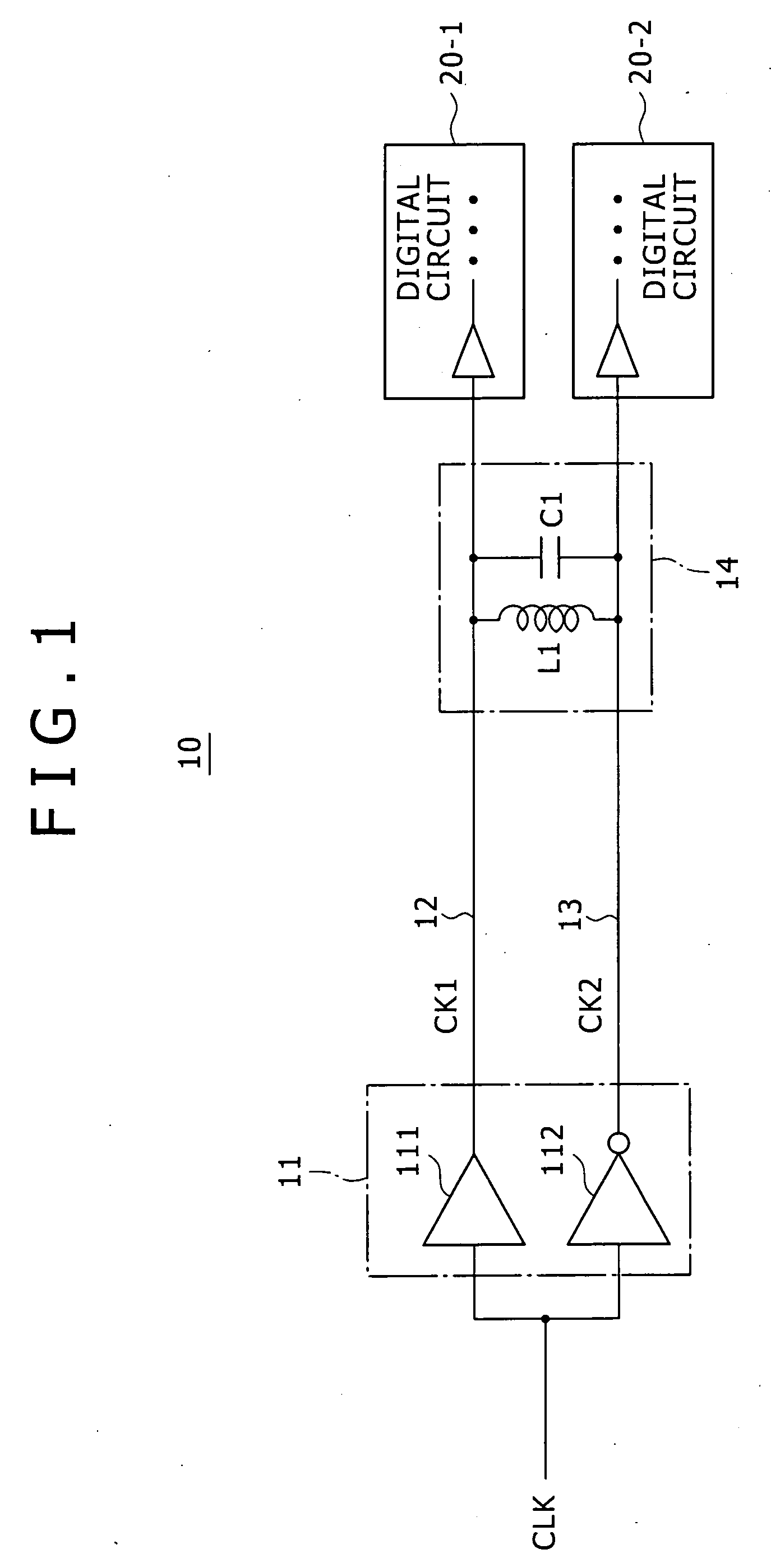
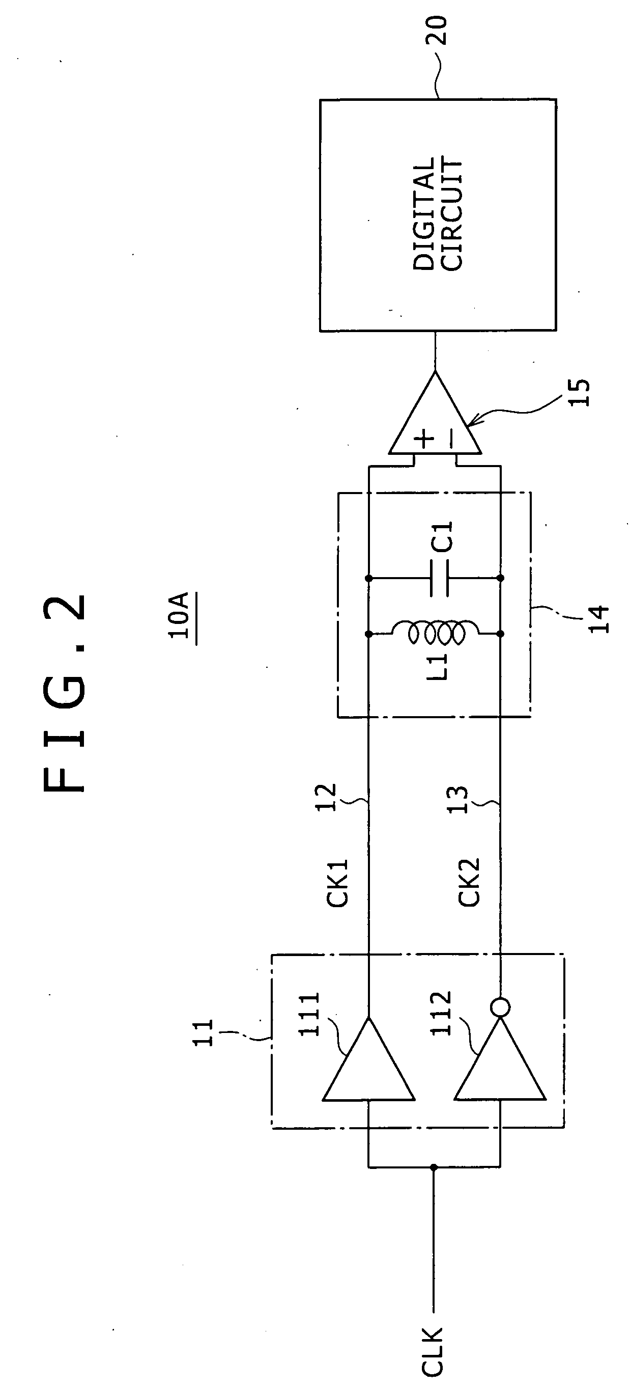
[0067]FIG. 2 shows an example of a configuration of another stabilized clock supplying apparatus to which the present invention is applied.

[0068]Referring to FIG. 2, the clock supplying apparatus 10A according to the second embodiment of the present invention is a modification to but is different from the clock supplying apparatus 10 according to the first embodiment described above in that a differential input comparator 15 serving as an amplitude adjustment section is interposed between the second end side of the first clock line 12 and the second clock line 13 and the clock input terminal of a digital circuit 20.

[0069]The first clock line 12 is connected at the second end side thereof to a non-inverting input (+) of the differential inputs of the differential input comparator 15 while the second clock line 13 is connected at the second end side thereof to an inverting input (−) of the differential input comparator 15. A clock after amplitude adjustment from the differential input...

third embodiment

[0087]FIG. 6 shows an example of a configuration of a further stabilized clock supplying apparatus to which the present third embodiment is applied.

[0088]Referring to FIG. 6, the stabilized clock supplying apparatus 30 of the third embodiment includes, as basic components thereof, a clock driver 31, a clock line 32 along which a clock from the clock driver 31 propagates, and a parallel resonance circuit 33 of an inductor L11 and a capacitor C11. The stabilized clock supplying apparatus 30 further includes a bias circuit 34 for generating a voltage close to an average value of a clock signal voltage, a power supply line 35 to which a power supply voltage VDD is supplied, a reference voltage line 36 which may be a ground potential line, and a digital circuit 40.

[0089]In the parallel resonance circuit 33, a first end of the inductor L11 and a-first electrode of the capacitor C11 are connected to the clock line 32, and a second end of the inductor L11 and a second electrode of the capac...


PUM


Abstract

Disclosed herein is a clock supplying apparatus for supplying a clock to a digital circuit, including: a differential clock driver; a first clock line along which a first clock of a positive phase from the clock driver propagates; a second clock line along which a second clock of a reverse phase from the clock driver propagates; and a parallel resonance circuit of an inductor and a capacitor. The inductor of the parallel resonance circuit is connected at a first end to the first clock line and at a second end to the second clock line. The capacitor of the parallel resonance circuit is connected at a first electrode to the first clock line and at a second electrode to the second clock line.

Description

CROSS REFERENCES TO RELATED APPLICATIONS[0001]The present invention contains subject matter related to Japanese Patent Application JP 2006-343409 filed with the Japan Patent Office on Dec. 20, 2006, the entire contents of which being incorporated herein by reference.BACKGROUND OF THE INVENTION[0002]1. Field of the Invention[0003]This invention relates to a clock supplying apparatus for supplying a clock to a digital circuit.[0004]2. Description of the Related Art[0005]A digital circuit which uses a high speed clock signal is influenced much by jitters of the clock, and the influence makes a cause of a drop of the operation speed or of a malfunction. Therefore, such countermeasures as described below have been taken heretofore.[0006]For a clock generation circuit, power supply lines are isolated from power supply lines for the other circuits in order to reduce jitters by power supply noise. Also such countermeasures as additional provision of a bypass controller, insertion of a power...

Claims


Application Information

Patent Timeline
IPC IPC(8): H03K3/00
CPCH03H7/0115H04L7/0008H03H7/1791H04L25/085H03H7/1775H04L7/027H03K3/013H04L25/02H04B3/02H04B3/30H03K19/003
Inventor KUMATA, ICHIRO
Owner SONY CORP
Why Eureka
Try Eureka