Light emitting diode based backlighting for color liquid crystal displays

a diode and liquid crystal display technology, applied in the field of color, transmissive liquid crystal display, can solve the problems of reduced color performance (70% ntsc), large size relative to the volume of the device, and suffers from ccfls

Inactive Publication Date: 2008-06-26
INTEMATIX
View PDF70 Cites 35 Cited by
  • Summary
  • Abstract
  • Description
  • Claims
  • Application Information

AI Technical Summary

Benefits of technology

[0015]The present invention arose in an endeavor to provide an LED-based backlight for a color emissive LCD which, at least in part, is an improvement on the known backlighting systems. Embodiments of the present invention are directed to an LED based backlight system for providing white light to a liquid crystal display (LCD). In contrast to the prior art backlighting systems, which use three different types of LEDs (red, green and blue), the present embodiments are directed to a system using only one or two types of LEDs (blue only or red and blue). In each case a green phosphor (photo-luminescent) material is excited by the blue LED to generate green light that combines with the blue and red light to make a white backlighting light.

Problems solved by technology

The trend of replacing CCFLs with LED based backlighting is driven by the fact CCFLs suffers from a number of disadvantages including reduced color performance (70% NTSC), large size relative to volume of the device, and the high cost of associated hardware, such as expensive drive circuits, etc.
However, such systems suffer from a number of drawbacks, including variation and unevenness of luminance and color.
These systems also require special consideration to attain the desired color mixing, intensity variation, and thermal stability, with a subsequently complicated sensor and feedback loop necessary for monitoring the color from each of the component LEDs.
To date, RGB LED backlighting systems are limited to a relatively small number of high-end applications.

Method used


Image

  • Light emitting diode based backlighting for color liquid crystal displays
  • Light emitting diode based backlighting for color liquid crystal displays
  • Light emitting diode based backlighting for color liquid crystal displays

Examples


Embodiment Construction

[0031]Embodiments of the invention are directed to LCD backlight units (BLU) using combinations of a blue LED and green emitting phosphors, to achieve a color performance between that of white LED and RGB LED based backlights. The color performance is comparable to that of a CCFL-based design, but without the complicated design features of the CCFL.

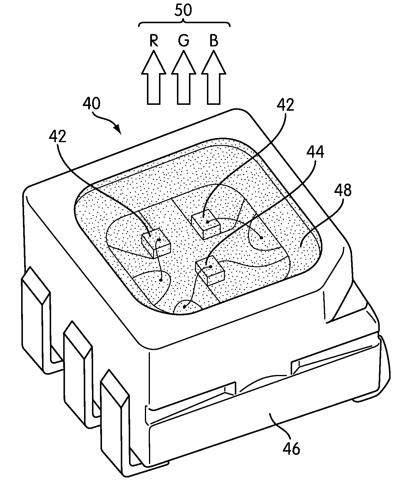
[0032]A color LCD backlight light source 40 in accordance with the invention is illustrated in FIG. 4. The backlight light source 40 comprises two blue LED chips 42, such as for example InGaN / GaN (indium gallium nitride / gallium nitride) based LED chips, which generate blue light of wavelength 400 to 465 nm and one red LED chip 44. The blue and red LED chips 42, 44 are co-packaged in a single lead-frame 46 and each is covered by a green phosphor 48 (indicated by a cross hatching of dashed lines). The phosphor material, which is in powdered form, can be mixed with a suitable transparent binder material such as a silicone material and the LE...


PUM

PropertyMeasurementUnit
of wavelengthaaaaaaaaaa
power levelaaaaaaaaaa
compositionaaaaaaaaaa

Abstract

A liquid crystal display backlight comprises: at least one blue light emitting diode (LED) operable to contribute blue light to white light generated by the backlight; a phosphor material which absorbs a portion of the blue light and emits green light which contributes green light to the white light generated by the backlight; and at least one red LED operable to contribute red light to the white light generated by the backlight. In one arrangement the red LED is replaced with a second phosphor material which absorbs a portion of the blue light and emits red light which contributes to the white light generated by the backlight. Many packaging configurations are possible.

Description

CROSS REFERENCE TO RELATED APPLICATION[0001]This Application claims the benefit of priority from U.S. Provisional Application No. 60 / 853,399 filed Oct. 19, 2006, the specification and drawings of which is incorporated herein by reference.BACKGROUND OF THE INVENTION[0002]1. Field of the Invention[0003]The present invention relates to color, transmissive liquid crystal displays (LCDs). More particularly the invention concerns backlighting systems for such displays which are based on light emitting diodes (LEDs).[0004]2. Description of the Related Art[0005]Color LCDs are based on picture elements, or “pixels”, formed by a matrix / array of liquid crystal (LC) cells. As is known the intensity of the light passing through a LC can be controlled by changing the angle of polarization of the light in response to an electrical field, voltage, applied across the LC. For a color LCD each pixel is actually composed of three “sub-pixels”: one red (R), one green (G), and one blue (B). Taken togethe...

Claims


Application Information

Patent Timeline
Patent Type & Authority Applications(United States)
IPC IPC(8): G02F1/13357H05B33/00H01L33/50
CPCG02F1/133603G02F1/133609H01L33/50H01L25/0753G02F2001/133614H01L2224/48091H01L2224/48247G02F1/133614H01L2924/00014G02F1/1335
Inventor LI, YI-QUNLIU, GORDONDONG, YI
Owner INTEMATIX
Why Eureka
Try Eureka