Magnetic recording method using ferromagnetic resonance and thin-film magnetic head for using the method

a magnetic recording and ferromagnetic resonance technology, applied in special recording techniques, instruments, nanoinformatics, etc., can solve the problems of saturated magnetic recording, degrading the thermal stability of the magnetization, increasing the coercive force of the magnetic recording layer, etc., and achieve high coercive force and high accuracy

Inactive Publication Date: 2008-06-26
TDK CORPARATION
View PDF8 Cites 44 Cited by
  • Summary
  • Abstract
  • Description
  • Claims
  • Application Information

AI Technical Summary

Benefits of technology

[0016]Accordingly, an object of the present invention is to provide a thin-film magnetic head capable of writing data with high accuracy on a magnetic recordin

Problems solved by technology

However, the more the magnetic particle is miniaturized, the more a heat fluctuation is generated in the magnetic particle due to the reduction in volume of the particle, thereby degrading thermal stability of the magnetization.
However, the increase in the magnetic anisotropy energy causes the increase in coercive force of the magnetic recording layer.
On the other hand, the write field intensity of the magnetic head is determined mainly by the saturation magnetic flux density of a soft-magnetic material that constitutes poles in the head, so that a saturated magnetic recording, which requires a write field intensity of about 2 times higher than the coercive force, is difficult to be implemented.
However, such heat-assisted magnetic recording system contains a variety of difficulties in terms of technology, which is a problem to be solved.
To actually realize the thin-film magnetic head for heat-assisted magnetic recording described above, generally, a minute electron discharge source, a laser light source or an optical component with high positioning accuracy and dimensional accuracy is needed to be formed inside the head, which becomes a large burden for the manufacturing process.
As a r

Method used


Image

  • Magnetic recording method using ferromagnetic resonance and thin-film magnetic head for using the method
  • Magnetic recording method using ferromagnetic resonance and thin-film magnetic head for using the method
  • Magnetic recording method using ferromagnetic resonance and thin-film magnetic head for using the method

Examples


first embodiment

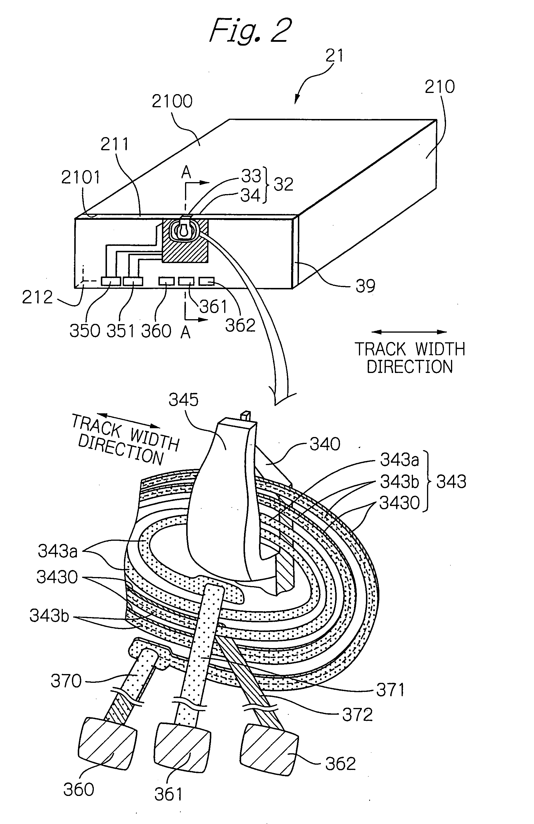
[0090]FIG. 3a shows a cross-sectional view taken along line A-A of FIG. 2 illustrating the structure of a major portion in the thin-film magnetic head according to the present invention, and FIG. 3b shows a plain view showing the structure in the slider end surface 211 as viewed from the ABS 2100 side.

[0091]As shown in FIG. 3a, reference numeral 210 denotes a slider substrate composed of ALTIC (Al2O3—TiC) or the like and has the ABS 2100 to be opposed to the magnetic disk surface. The MR effect element 33, the electromagnetic coil element 34 and the overcoat 39 for protecting these elements are mainly formed on / above the element formation surface 2101 of this slider substrate 210.

[0092]The MR effect element 33 includes an MR effect multilayer 332 and a lower shield layer 330 and an upper shield layer 334 which sandwich this multilayer 332. The MR effect multilayer 332 includes a current-in-plane (CIP) giant magnetoresistive (GMR) multilayered film, a current-perpendicular-to-plane (...

second embodiment

[0122]FIG. 5 shows a cross-sectional view taken along the line A-A of FIG. 2, illustrating a main portion of the thin-film magnetic head according to the present invention.

[0123]As shown in FIG. 5, this embodiment has the same structure as the first embodiment shown in FIG. 3 except that an auxiliary shield layer 346′ and a main magnetic pole layer 340′ are connected magnetically. Therefore, the description of other structure than the both layers will not be repeated.

third embodiment

[0124]According to this embodiment, as shown in FIG. 5, a portion separated from an end portion on the slider end surface 211 side of a main pole yoke layer 3400′ possessed by a main magnetic pole layer 340′ is connected to the auxiliary shield layer 346′ magnetically. In this case, the shunt effect of magnetic flux possessed by a leading shield portion 3460′ which is an end portion on the slider end surface 211 side of the auxiliary shield layer 346′ is further increased. As a consequence, the magnetic field gradient of the write magnetic field can be increased even if the leading gap length DLG is not made so small, thereby increasing the possibility of the head design. FIG. 6 shows a cross-sectional view taken along the line A-A illustrating a main portion of the thin-film magnetic head according to the present invention.

[0125]According to this embodiment as shown in FIG. 6, in addition to the first embodiment shown in FIG. 3, provided are: a leading-side write coil 50 as a write...


PUM


Abstract

Provided is a thin-film magnetic head capable of writing data with high accuracy on a magnetic recording medium having high coercive force without heating. The head comprises an electromagnetic coil element comprising: a main magnetic pole; an auxiliary magnetic pole; and a write coil formed so as to pass through at least between the main magnetic pole and the auxiliary magnetic pole, for generating the write magnetic field. In this head, a part of the write coil has a layered structure of: a resonance coil layer for generating a resonance magnetic field having ferromagnetic resonance frequency of a magnetic recording layer of a magnetic recording medium or having a frequency in the vicinity thereof; and a write coil layer. And further, the resonance coil layer and the write coil layer sandwich an insulating layer therebetween.

Description

PRIORITY CLAIM[0001]This application claims priority from Japanese patent application No. 2006-344016, filed on Dec. 21, 2006, which is incorporated herein by reference.BACKGROUND OF THE INVENTION[0002]1. Field of the Invention[0003]The present invention relates to a thin-film magnetic head for writing data on a magnetic recording medium with high coercive force to stabilize the magnetization thermally, a head gimbal assembly (HGA) having this thin-film magnetic head and a magnetic recording / reproducing apparatus having this HGA. Further, the present invention relates to a magnetic recording method for writing data on such a magnetic recording medium with high coercive force.[0004]2. Description of the Related Art[0005]Further improvement of the performance and characteristic of thin-film magnetic heads and magnetic recording media has been demanded with acceleration of the recording density of magnetic recording / reproducing apparatuses represented by magnetic disk drive apparatuses...

Claims


Application Information

Patent Timeline
IPC IPC(8): G11B5/33
CPCB82Y10/00G11B5/1278G11B2005/0005G11B5/743G11B5/3123
Inventor SATO, ISAMUROPPONGI, TETSUYAWATABE, YUICHIOTA, NORIKAZUIKEDA, HIROSHIMATSUZAKI, MIKIO
Owner TDK CORPARATION
Why Eureka
Try Eureka