Shake compensating device for optical devices

a compensating device and optical technology, applied in the direction of mirrors, instruments, printers, etc., can solve the problems of difficult compensation for large shakes, easy deterioration of image quality, and easy complex mechanical mechanisms, and achieve the effect of simple structur

Inactive Publication Date: 2008-06-26
OLYMPUS CORP
View PDF5 Cites 18 Cited by
  • Summary
  • Abstract
  • Description
  • Claims
  • Application Information

AI Technical Summary

Benefits of technology

[0010]It is, therefore, a primary object of the present invention to provide a shake compe

Problems solved by technology

However, the device using the variable angle prism has the problem that since a ray of light transmitted through the prism is conducted to the photographic lens, image quality is easily deteriorated due to chromatic aberration.
Hie 4-211230 is such that since the displacement of the bimorph

Method used


Image

  • Shake compensating device for optical devices
  • Shake compensating device for optical devices
  • Shake compensating device for optical devices

Examples


Embodiment Construction

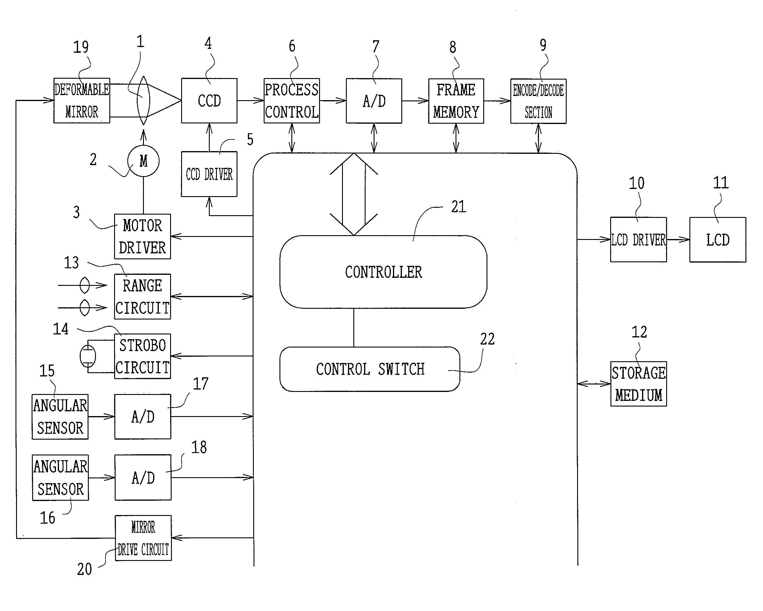
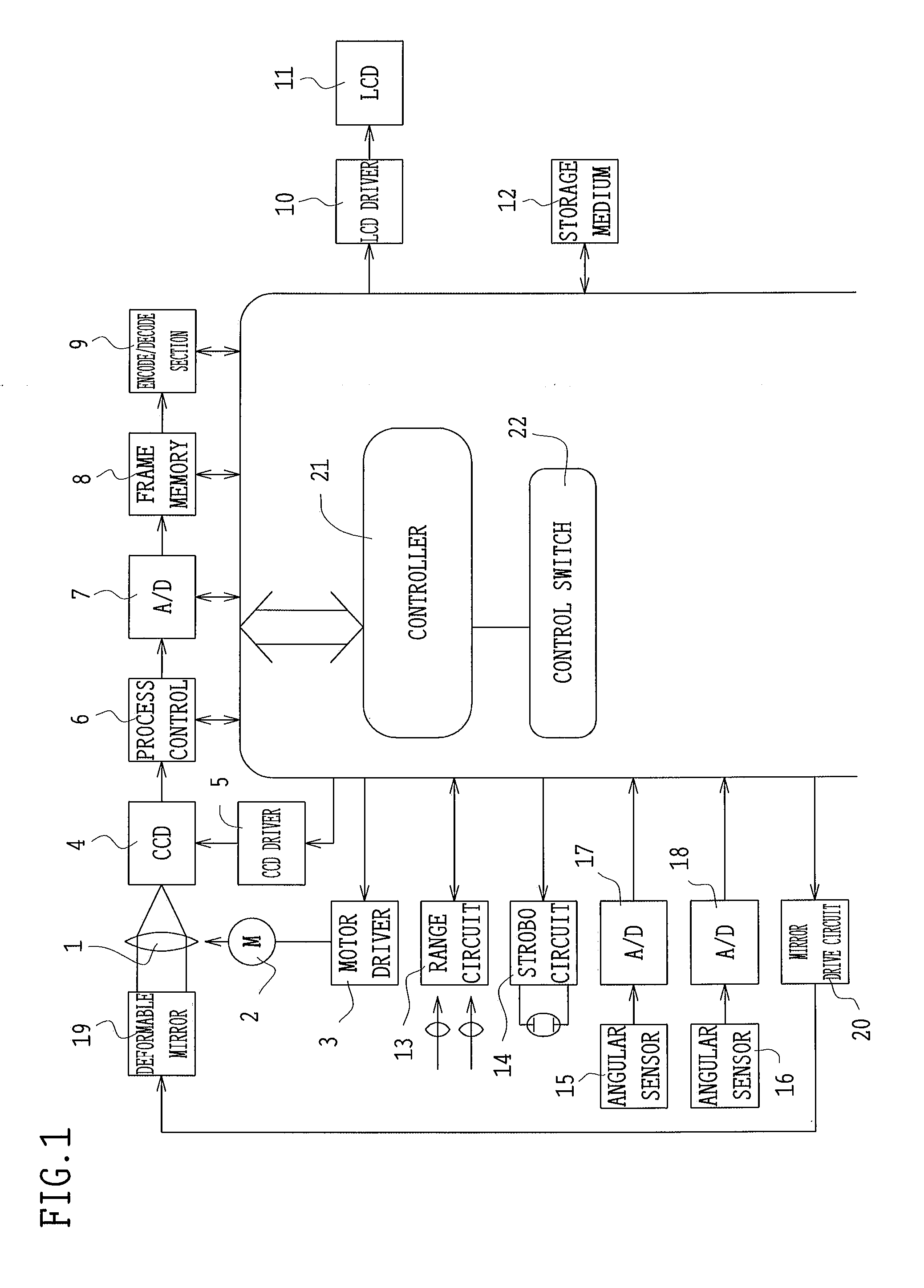
[0081]FIG. 1 shows a system construction inside a camera to which the shake compensating device of the present invention is applied. The camera includes a photographic lens 1, a motor 2, a motor driver 3, a CCD 4, a CCD driver 5, a process control circuit 6, an A / D converter 7, a frame memory 8, an image encode / decode section 9, an LCD driver 10, an LCD 11, a storage medium 12, a range circuit 13, a stroboscope emitting circuit 14, angular velocity sensors 15 and 16, A / D converters 17 and 18, a deformable mirror 19, a deformable mirror driving circuit 20, a controller 21, and a control switch 22.

[0082]The motor 2 is adapted to adjust the focus position of the photographic lens 1. The motor driver 3 is a driving circuit for driving the motor 2. The CCD 4 is an image sensor for converting an image of an object into an electric signal. The CCD driver 5 is a driving circuit for driving the CCD 4. The process control circuit 6 is adapted to make the separation of a color signal, gain con...


PUM


Abstract

A shake compensating device for optical devices includes an optical system for forming an image of an object; a reflecting surface placed in the optical path of the optical system, a first substrate having a first electrode, placed adjacent to the reflecting surface; a second substrate fixed to an optical device, placed opposite to the first substrate and having a second electrode at a position opposite to the first electrode; a voltage control circuit for applying voltages across the first electrode and the second electrode, one of which is divided into a plurality of electrodes; and a detecting unit for detecting the shake angle of the optical device. In this case, the voltage control circuit controls the voltages applied across the divided electrodes and the other electrode opposite thereto in accordance with the output of the detecting unit.

Description

[0001]This is a continuation of U.S. application Ser. No. 10 / 198,068, which was filed Jul. 19, 2002, the contents of which are incorporated herein by reference in their entirety.BACKGROUND OF THE INVENTION[0002]1. Field of the Invention[0003]This invention relates to a device for compensating a shake caused by hand-held use on photographing in an optical device such as a camera, which refers to a silver halide firm camera, a digital camera, a TV camera, a camcorder or a gastrocamera.[0004]2. Description of the Related Art[0005]Conventional devices for compensating a shake caused by hand-held use on photographing in an optical apparatus such as a camera are available in those in which a variable angle prism placed in front of a photographic lens is used (for example, Japanese Patent Kokai No. Hei 5-181094) and those in which a reflecting mirror placed in front of the photographic lens is used (for example, Japanese Patent Kokai No. Hei 4-211230).[0006]A shake compensating device disc...

Claims


Application Information

Patent Timeline
IPC IPC(8): G03B17/00G02B7/18
CPCG02B27/646G03B17/00G03B5/00
Inventor YAMASAKI, MASAFUMIKANEKO, SHINJINISHIOKA, KIMIHIKO
Owner OLYMPUS CORP
Why Eureka
Try Eureka