
Lithium storage battery comprising a current-electrode collector assembly with expansion cavities and method for producing same

Inactive Publication Date: 2008-06-26
COMMISSARIAT A LENERGIE ATOMIQUE ET AUX ENERGIES ALTERNATIVES
View PDF9 Cites 79 Cited by
  • Summary
  • Abstract
  • Description
  • Claims
  • Application Information

AI Technical Summary

Benefits of technology

[0018]The object of the invention is to provide a lithium storage battery remedying the shortcomings of the prior art and in particular limiting the stresses exerted on the electrolyte while at the same time having high performances and being easy to implement.

Problems solved by technology

With such a storage battery, it is for example impossible to perform a solder re-flow process used to assemble integrated circuits.
In addition, lithium presents a strong reactivity to air, which is penalizing for encapsulation, and it has to be deposited by thermal evaporation, which complicates the manufacturing process of the storage batteries.
These volume expansions do however generate large stresses on the electrolyte, which can lead to cracks and therefore to short-circuits making the battery unusable.
Such phenomena can also occur in a Li-Free storage battery, as formation of lithium on the blocking metallic layer results in protuberances, also causing large stresses and potential breaking of the electrolyte.
More particularly, the problems of stresses in Li-ion storage batteries and Li-Free storage batteries lead to short-circuit rates of about 90% after 1,000 charging-discharging cycles, as underlined by U.S. Pat. No. 6,770,176 B2.
Such a solution is not however satisfactory, for it multiplies the number of layers to be deposited and the number of targets to be used for depositing the electrolyte.
It therefore increases the cost of the production method.
However this solution is not satisfactory, for, as indicated in U.S. Pat. No. 6,713,987, the thickness of the anode can be non uniform, which generates stresses and leads to short-circuits.
Moreover, deposition of the additional layer increases the cost of the lithium storage battery and reduces the energy density factor of the storage battery.
Producing the storage battery with its encapsulation enclosure is however complicated.
Furthermore, such a storage battery occupies a large amount of space and can not be combined with an integrated circuit for example.
Fabrication of such an anode is however complex to implement.
In addition, this growth and in particular the height and perpendicularity of the nanotubes or nanowire with respect to the current collector substrate are not always well controlled.

Method used


Image

  • Lithium storage battery comprising a current-electrode collector assembly with expansion cavities and method for producing same
  • Lithium storage battery comprising a current-electrode collector assembly with expansion cavities and method for producing same
  • Lithium storage battery comprising a current-electrode collector assembly with expansion cavities and method for producing same

Examples


first embodiment

[0035] the expansion cavities are formed by the recessed zones of the current collector and the continuous thin layer of the electrode is arranged on said current collector to cover said recessed zones.

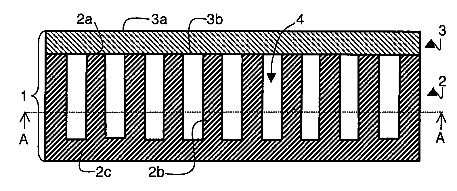
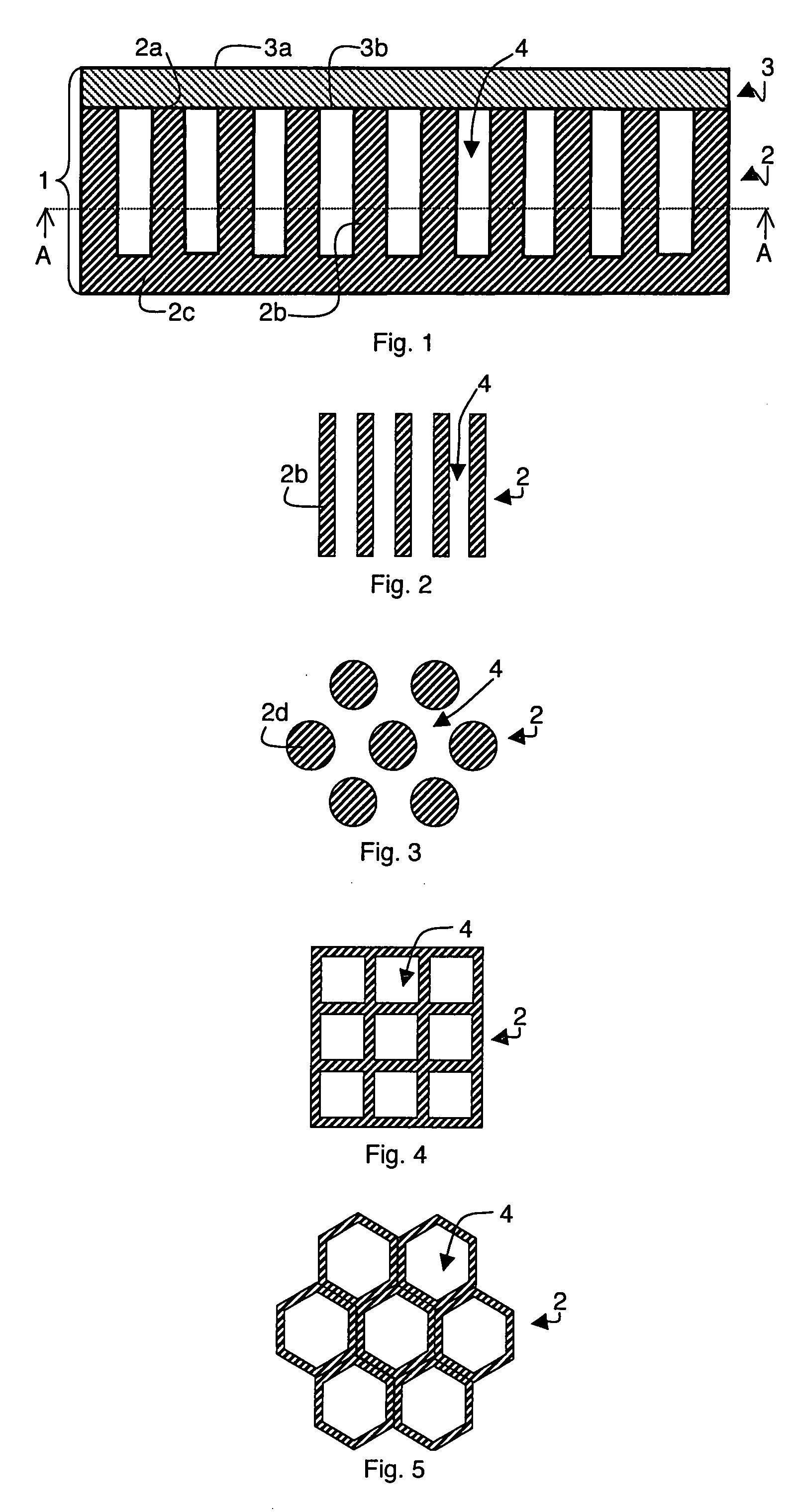
[0036]Thus, as represented in FIGS. 1 and 2, an assembly 1 for a lithium storage battery comprises a stack of two thin layers respectively forming current collector 2 and electrode 3. The electrode, formed by continuous thin layer 3, comprises flat and parallel opposite first and second surfaces 3a and 3b. First surface 3a is free and is designed to be in contact with the electrolytic membrane. Second surface 3b is in contact with surface 2a of current collector 2, in which the openings or recessed zones 4 constituting the expansion cavities are made. Second surface 3b of electrode 3 is thus arranged on the free ends of the side walls delineating the recessed zones in current collector 2.

[0037]Expansion cavities 4 are thus formed in current collector 2 and they extend up to surface 2a...

second embodiment

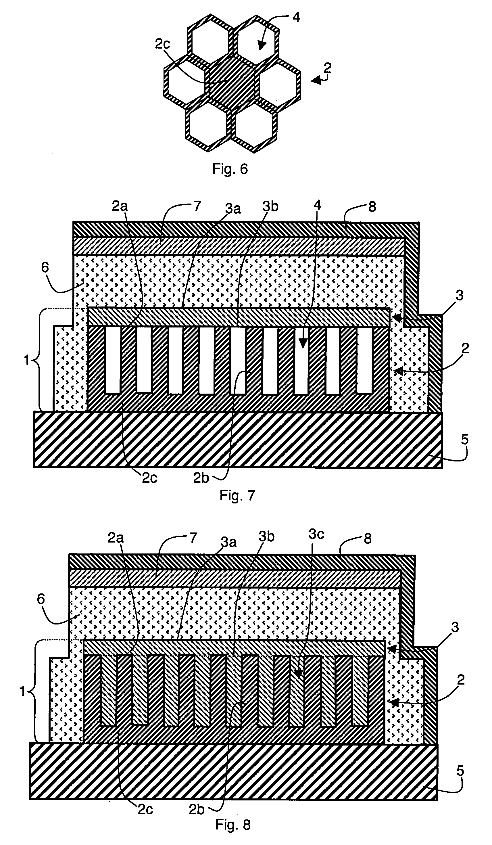
[0052]Thus, represented in FIG. 11, assembly 1 can be formed by a current collector 2 comprising a surface 2a provided with a plurality of recessed zones and an electrode formed by a continuous thin layer 9 obtained by conformal deposition on said surface 2a of collector 2. The thin layer 9 is thus deposited on the whole surface 2a of the collector. It thereby covers the whole of the walls of the current collector delineating the recessed zones and the free ends of side walls 2b. Expansion cavities 10 are thus formed in the recessed zones of the current collector by the part of continuous thin layer 9 covering the walls of said zones. In this case, expansion cavities 10 are open, and do not comprise any upper walls. More particularly, the thickness of continuous thin layer 9 is selected such as to allow a free space between the two parts of thin layer 9 arranged facing a recessed zone, said space forming an expansion cavity.

[0053]In FIG. 11, the structure of current collector 2 is ...


PUM


Abstract

A lithium storage battery comprises a stack formed by a current collector comprising recessed zones, an electrode and a plurality of expansion cavities for the material forming the electrode. Each expansion cavity comprises at least one wall formed by a part of the electrode. Preferably the electrode is an electrode formed by at least one material able to insert and de-insert Li+ ions, the volume of which material increases when Li+ ions are inserted. The empty volume of the expansion cavities can thus be at least partially filled by a part of the material forming the electrode when Li+ cations are inserted in the material. The expansion cavities are formed in the recessed zones of the current collector.

Description

BACKGROUND OF THE INVENTION[0001]The invention relates to a lithium storage battery comprising at least an electrolyte and a stack comprising an electrode, a current collector comprising a plurality of recessed zones delineated by side walls each comprising a free end, and expansion cavities for the electrode.[0002]The invention also relates to a method for producing one such storage battery.STATE OF THE ART[0003]Microbatteries in the form of thin films are based on the principle of insertion and de-insertion (or intercalation and de-intercalation) of an alkaline metal ion or of a proton in the positive electrode. The main known systems are lithium storage batteries using the Li+ cation as ionic species. The components of these lithium storage batteries (current collectors, positive and negative electrodes and electrolyte) are generally in the form of a stack of thin layers with a total thickness of about 15 μm. The stack is protected from the external environment, and specifically ...

Claims


Application Information

Patent Timeline
IPC IPC(8): H01M4/38H01M6/00H01M4/13H01M4/134H01M10/052H01M10/0562H01M10/0585H01M10/36
CPCH01M4/13H01M4/134H01M4/70H01M10/0436Y02E60/122H01M10/0562H01M10/0585H01M2004/027H01M10/052Y02E60/10Y02P70/50
Inventor SALOT, RAPHAELGAILLARD, FREDERICBANCEL, STEPHANE
Owner COMMISSARIAT A LENERGIE ATOMIQUE ET AUX ENERGIES ALTERNATIVES
Learn More