Cmp pad conditioners and associated methods

a conditioner and pad technology, applied in the field of cmp pad conditioners, can solve the problems of forming asperities in the cmp pad, reducing the degree of so as to reduce minimize the compression of the cmp pad. , the effect of reducing the compression of the cmp pad

Inactive Publication Date: 2008-06-26
SUNG CHIEN MIN
View PDF55 Cites 63 Cited by
  • Summary
  • Abstract
  • Description
  • Claims
  • Application Information

AI Technical Summary

Benefits of technology

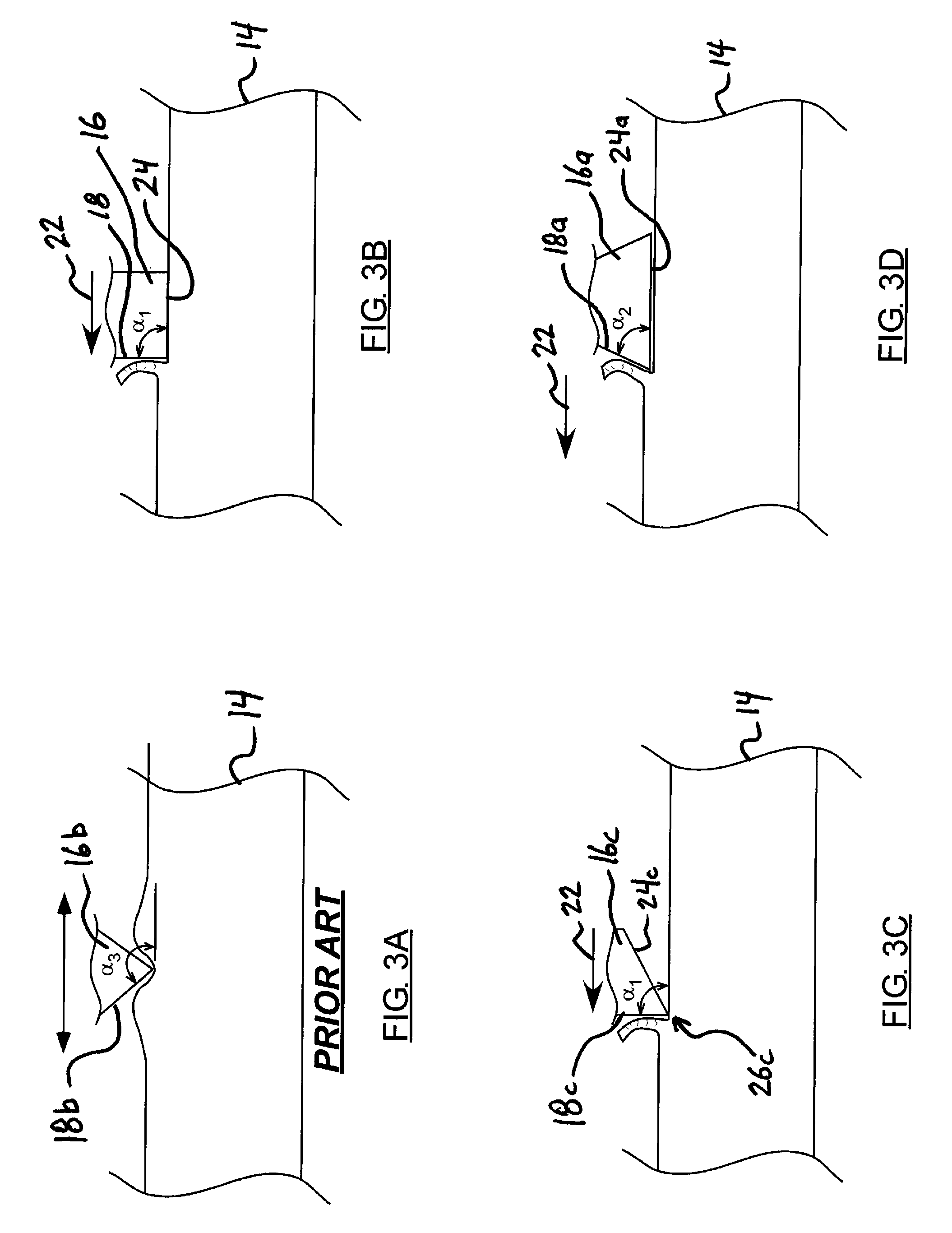
[0004]In accordance with one embodiment, the present invention provides a method of reducing a degree of compression of a CMP pad during conditioning of the CMP pad, comprising: engaging the CMP pad with at least one superhard cutting element, the cutting element including a cutting face, the cutting face being angled at 90 degrees or less relative to a finished surface of the CMP pad; and moving the CMP pad and the cutting element relative to one another in a direction resulting in removal of material from the CMP pad with the cutting face to thereby condition the CMP pad.
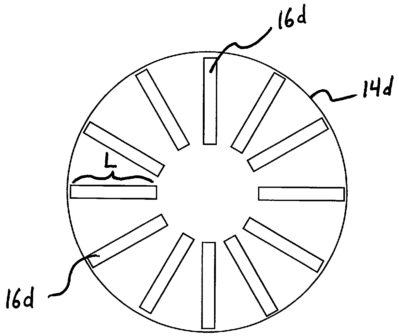
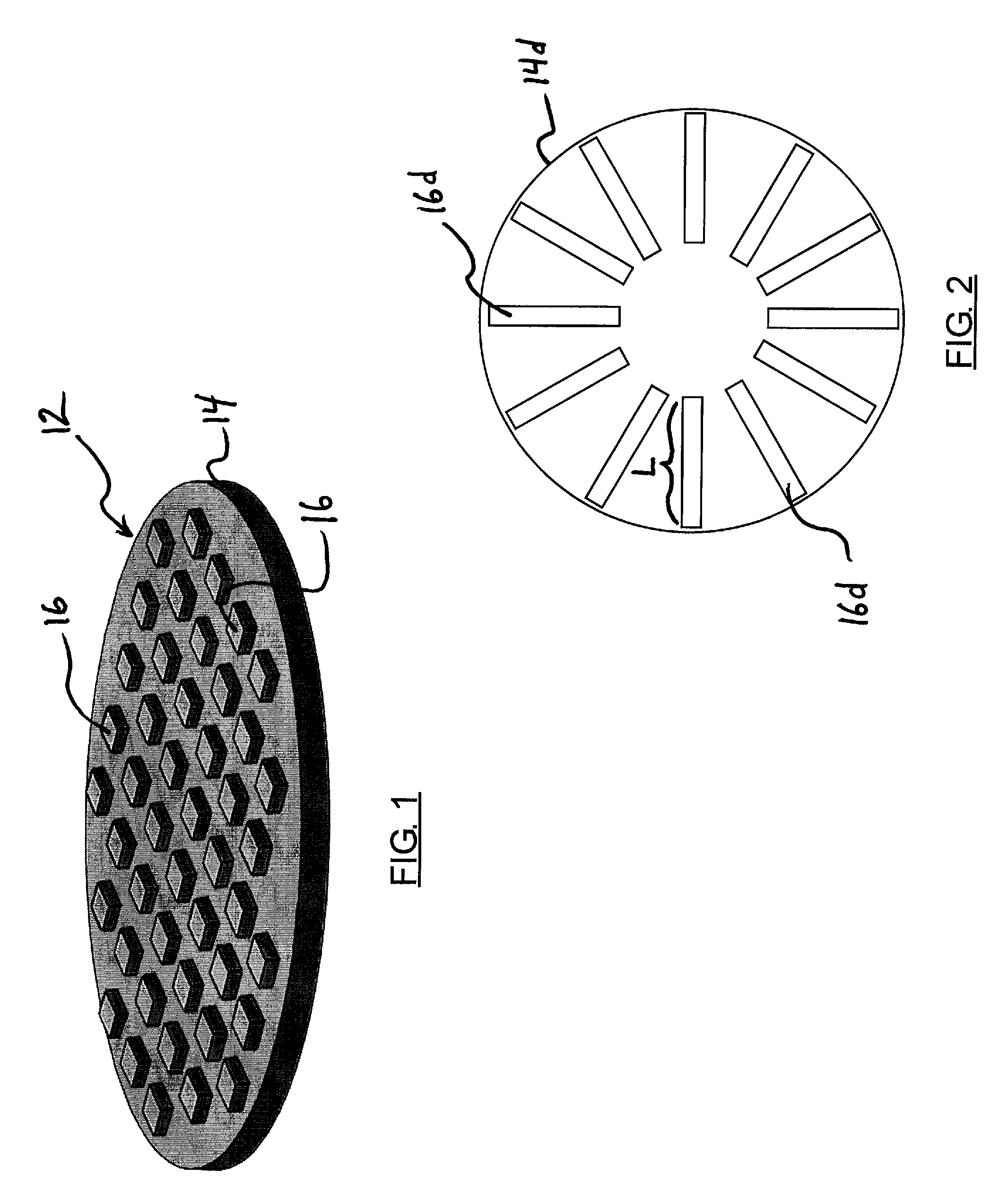
[0005]In accordance with another aspect, the present invention provides a pad conditioner for removing material from a CMP pad while minimizing compression of the CMP pad, including a base and a plurality of cutting elements, extending from the base. The cutting elements can each having a cutting face angled at 90 degrees or less relative to a finished surface of the CMP pad. The faces of the cutting elements can be oriented such that relative movement of the pad conditioner and the CMP pad results in removal of material from the CMP pad with the cutting faces to thereby condition the CMP pad.
[0006]In accordance with another aspect of the invention, a method of reducing a degree of compression of a CMP pad during conditioning of the CMP pad is provided, including: engaging the CMP pad with a plurality of superhard cutting elements formed from a polycrystalline diamond compact, each of the cutting elements including a cutting face, the cutting faces being angled at 90 degrees or less relative to a finished surface of the CMP pad; and moving the CMP pad and the cutting element relative to one another in a direction resulting in removal of material from the CMP pad with the cutting face to thereby condition the CMP pad.

Problems solved by technology

This downward force results in compression of the pad material.
The compressed pad material is correspondingly more difficult to cut smoothly and evenly, with often large pieces being torn resulting in asperities being formed in the CMP pad.
These asperities can damage the silicone wafer to be conditioned by the pad.
As such, the relatively soft pad must be compressed, resulting in significant deformation (elastic and plastic) before it is penetrated by the diamond tips.
Due to the resulting dragging and tearing, the cutting path remaining on the pad is jagged with varying width and depth.

Method used


Image

  • Cmp pad conditioners and associated methods
  • Cmp pad conditioners and associated methods
  • Cmp pad conditioners and associated methods

Examples


example 1

[0073]A PCD compact with sintered polycrystalline diamond coupled with cemented tungsten carbide substrate is used as a blank for EDM machining. The compact disk has a diameter of 34 mm (e.g. Adico), 52 mm (e.g. Adico), 60 mm (e.g. Diamond Innovations), 74 mm (e.g. Element Six), or 100 mm (e.g. Tomei Dia). The typical PCD layer is 400-600 microns thick. The total thickness (including the WC substrate) can be 1.6 mm or 3.2 mm as standard materials.

[0074]The PCD surface is fine polished to have an Ra less than about 1 micron. The blank is wire-EDM cut to form zigzag pattern with tip-to-tip distance of about 400 microns and tip-to-valley depth of about 100 microns. The tip angle can be 60, 70, 60, 90 or 100 degrees (relative to a finished surface applied to a pad), which can be varied by the computer setting for traversing the PCD blank. The zigzag pattern produces symmetrical profiles on the vertically sliced blades. The blade (e.g., cutting element) thickness can be less than about 1...

example 2

[0080]A process similar to that described in Example 1 is used, except that a WC blank is used instead of PCD. The WC blank contains a low amount of cobalt (e.g. 6 wt %). The straight blades are set in a fixture and placed in a CVD reactor with methane (1%) hydrogen mixture that is thermally decomposed and dissociated to form carbon and atomic hydrogen. The CVDD coated WC will deposit diamond grains with sharp cutting tips that can be spaced by controlling the nucleation density, sparse nuclei distribution, larger grains, and higher protrusion and further separation. The diamond grains can range from nano crystalline (i.e. the edge is straight) to grains with larger than 10 microns. The low cobalt amount in WC can help diamond retaining by avoiding the back conversion due to its catalystic ability.

example 3

[0081]A process similar to that described in Example 2 is used, except that the blade is sliced from a silicon infiltrated SiC blank.


PUM

PropertyMeasurementUnit
angleaaaaaaaaaa
angleaaaaaaaaaa
angleaaaaaaaaaa

Abstract

A method of reducing a degree of compression of a CMP pad during conditioning of the CMP pad comprises engaging the CMP pad with at least one superhard cutting element, the cutting element including a cutting face, the cutting face being angled at 90 degrees or less relative to a finished surface of the CMP pad; and moving the CMP pad and the cutting element relative to one another in a direction resulting in removal of material from the CMP pad with the cutting face to thereby condition the CMP pad.

Description

[0001]Priority is claimed of copending U.S. Provisional Patent Application No. 60 / 866,202, filed Nov. 16, 2006, which is hereby incorporated herein in its entirety.FIELD OF THE INVENTION[0002]The present invention relates generally to CMP pad conditioners used to remove material from (e.g., smooth, polish, dress, etc.) CMP pads. Accordingly, the present invention involves the fields of chemistry, physics, and materials science.BACKGROUND OF THE INVENTION[0003]Abrasive materials are used in wide range of polishing, planing, dressing, or conditioning processes. As one example, the semiconductor industry currently spends in excess of one billion U.S. Dollars each year manufacturing silicon wafers that must exhibit very flat and smooth surfaces. Known techniques to manufacture smooth and even-surfaced silicon wafers are plentiful. The most common of these involves the process known as Chemical Mechanical Polishing (CMP) which includes the use of a polishing pad in combination with an ab...

Claims


Application Information

Patent Timeline
Patent Type & Authority Applications(United States)
IPC IPC(8): B24B1/00
CPCB24B53/017
Inventor SUNG, CHIEN-MIN
Owner SUNG CHIEN MIN
Why Eureka
Try Eureka