Wireless millimeter wave communication system

a communication system and millimeter wave technology, applied in the direction of repeater circuits, line-transmission details, transmission monitoring, etc., can solve the problems of not justifying the design and construction of fiber optic trunk lines can often take many months, and the cost of fiber optic trunk lines is high, so as to minimize the size of the transceiver, minimize the adverse effect of tower sway, and maximize the beam divergence

Inactive Publication Date: 2008-06-26
TREX ENTERPRISES CORP
View PDF5 Cites 28 Cited by
  • Summary
  • Abstract
  • Description
  • Claims
  • Application Information

AI Technical Summary

Benefits of technology

[0017]The transceiver is designed for use in wireless communication systems operating in the E-band spectrum consistent with the FCC rules regulating the 71-76 GHz and 81-86 GHz bands. The radio uses a single aperture to transmit radiation in one of the two bands, and receive radiation in the other of the bands. The counterpart radio used to form a l

Problems solved by technology

However, the construction of fiber optic trunk lines is expensive (sometimes very expensive) and the design and the construction of these lines can often take many months especially if the route is over private property or produces environmental controversy.
Often the expected revenue from the potential users of a particular trunk line under consideration does not justify the cost of the fiber optic trunk line.
In conjunction with the above availability requirements, weather-related attenuation limits t

Method used


Image

  • Wireless millimeter wave communication system
  • Wireless millimeter wave communication system
  • Wireless millimeter wave communication system

Examples


Embodiment Construction

E-Band Millimeter Wave Communication

[0046]United States Federal Communication Commission (FCC) regulations define a minimum 3 dB divergence angle of 1.2 degrees, a minimum antenna gain of G=43 dBi, side lobe reduction between 1.2 degrees and 5 degrees of G-28, and side lobe reduction of 35 dB between 5 and 10 degrees off axis. (There are further side lobe reduction requirements at larger angles).

Lens-Based Transceiver

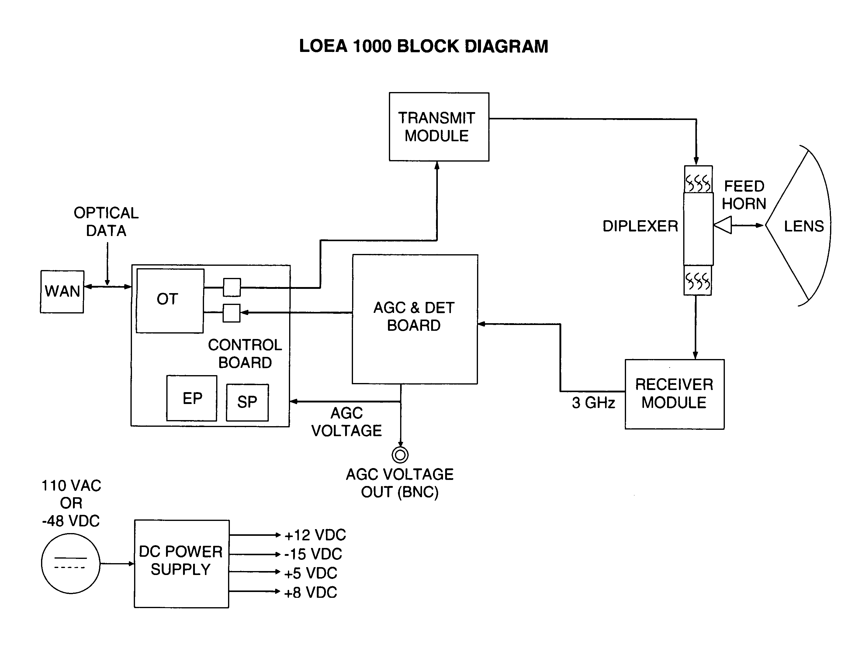
[0047]Drawings of two lens-based transceivers are shown at 12 and 14 in FIGS. 8A and 8B. Components include cylindrical housing 42, lens 31, feed horn 30, transmit electronics 24A, receive electronics 24B, diplexer unit 28, interface electronics module 32, Ethernet or fiber optics input-output 34, mount unit 40, azimuth adjustment 38 and elevation adjustment 36. Outgoing beam is shown at 13 and incoming beam is shown at 15 and the beam width is indicated at 23. Two prospective views of the transceiver showing these components are provided in FIGS. 9A and 9B. FIG. 10 des...


PUM


Abstract

A lens-based millimeter wave transceiver for use in wireless communication systems operating in the E-band spectrum consistent with the FCC rules regulating the 71-76 GHz and 81-86 GHz bands. The transceiver includes a single lens adapted for transmission of millimeter radiation to form communication beams in one band of either a band of about 71-76 GHz or a band of 81-86 GHz and for collection and focusing of millimeter wave radiation from communication beams in the other of the two bands. It includes a feed horn adapted to broadcast millimeter radiation through said single lens and to collect incoming millimeter wave radiation collected and focused by said single lens. A millimeter wave diplexer separates incoming and outgoing millimeter wave radiation.

Description

[0001]The present invention relates to communication systems with wireless communication links and specifically to high data rate point-to-point links. This application is a continuation-in-part application of Ser. No. 11 / 249,787 and Ser. No. 11 / 327,816 filed Jan. 6, 2006, the latter two of which are continuations in part of Ser. No. 10 / 799,225 filed Mar. 12, 2004, now U.S. Pat. No. 7,062,293, which was a continuation-in-part of Ser. No. 09 / 952,591 filed Sep. 14, 2001, now U.S. Pat. No. 6,714,800 that in turn was a continuation-in-part of Ser. No. 09 / 847,629 filed May 2, 2001 now U.S. Pat. No. 6,556,836, and Ser. No. 09 / 882,482 filed Jun. 14, 2001 now U.S. Pat. No. 6,665,546. This application also claims the benefit of Provisional Application Ser. No. 60 / 876,916 filed Dec. 22, 2006.BACKGROUND OF THE INVENTIONLocal Wireless Radio Communication[0002]Local wireless communication services represent a very rapidly growing industry. These services include paging and cellular telephone ser...

Claims


Application Information

Patent Timeline
IPC IPC(8): H04B1/38
CPCH01Q19/08H01Q19/062
Inventor KOREVAAR, ERICTINOCO, EDUARDOCHEDESTER, RICHARDKOLINKO, VLADIMAR
Owner TREX ENTERPRISES CORP
Why Eureka
Try Eureka