Neutron irradiative methods and systems

a neutron irradiation and neutron beam technology, applied in the direction of material analysis, material analysis using wave/particle radiation, instruments, etc., can solve the problems of non-metallic articles such as explosives or narcotics that are not detectable by such methods, explosives and narcotics, as a general rule, do not have readily distinguishable ionizing photons, etc., to achieve low false alarm rate, capture cross-section, and high incident neutron

Active Publication Date: 2008-07-03
RGT UNIV OF MICHIGAN
View PDF5 Cites 30 Cited by
  • Summary
  • Abstract
  • Description
  • Claims
  • Application Information

AI Technical Summary

Benefits of technology

[0008]While the discussion above describes the use of thermal neutrons (typically with energies below about 0.025 eV, the most probable energy) for activation analysis, higher energy (fast) neutrons may also be used. High energy neutrons have the potential advantage that they can penetrate further and thus may interrogate deeper into the interior of larger containers. In fact, their usage may be required for the interrogation of very large samples. Their use, however, suffers from the problems with persistence of lingering radioactivity in the object of interest and may pose other problems when the large neutron flux interacts with metals or heavy elements in the vicinity as described for methods using thermal neutrons described above. Furthermore, the capture cross-section for fast neutrons is often lower than for low energy neutrons and thus require an even higher incident neutron flux for reliable detection with low false alarm rates. Therefore, the target must be irradiated with large numbers of neutrons in order to get usable neutron activation data. This brings with it problems of unintended high flux neutron scattering that, for safety, requires substantially greater shielding, and thus a larger equipment footprint or personnel stand-off distances. It should also be understood that techniques employing neutrons having energies between those of fast and thermal suffer from some of the limitations of both techniques.
[0009]Inelastic neutron scattering (INS) is the process in which neutrons interact with the nuclei in object of interest producing an excited nuclear state, which then emit neutrons with a lower energy and g

Problems solved by technology

Magnetic inspection techniques can be useful for detecting metallic articles, such as weapons, but non-metallic articles such as explosives or narcotics are not detectable by such methods.
Furthermore, explosives and narcotics, as a general rule, do not have readily distinguishable ionizing photon (X-ray or gamma ray) absorption characteristics, unless examined using low energy photons.
However, the use of low energy photons limits such examination to smaller objects and, thus, may prove difficult to distinguish contraband and normal items of commerce.
Both magnetic and X-ray and ionizing photon methods may not provide sufficient functionality and/or reliability in the detection of many types of contraband.
This approach is capable of identifying various elemental compositions, but its practical utility is largely confined to low volume, low throughput applications as in a laboratory environment due, in part, to the high rate of attenuation of the low energy neutrons.
Furthermore, a very large number of the possible thermal neutron interactions result in the production of radioactive nuclei that have persistent radioactivity.
The fundamental process thus requires that the sample be made radioactive and the induced activity of many common materials, particularly metals, persists well beyond the inspection period and thus can present a health hazard.
Items in the environment near the sample may similarly become radioactive.
The duration of the radioactivity of many benign inspected items may be quite long.
Furthermore, neutron activation analysis is not very efficient for detecting nitrogen or carbon, two of the major components of explosives and narcotics, because nitrogen o

Method used


Image

  • Neutron irradiative methods and systems
  • Neutron irradiative methods and systems
  • Neutron irradiative methods and systems

Examples


Embodiment Construction

[0025]The following description is merely exemplary in nature and is not intended to limit the present disclosure, application, or uses.

Neutron Elastic Scattering (NES)

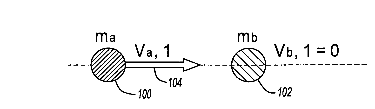
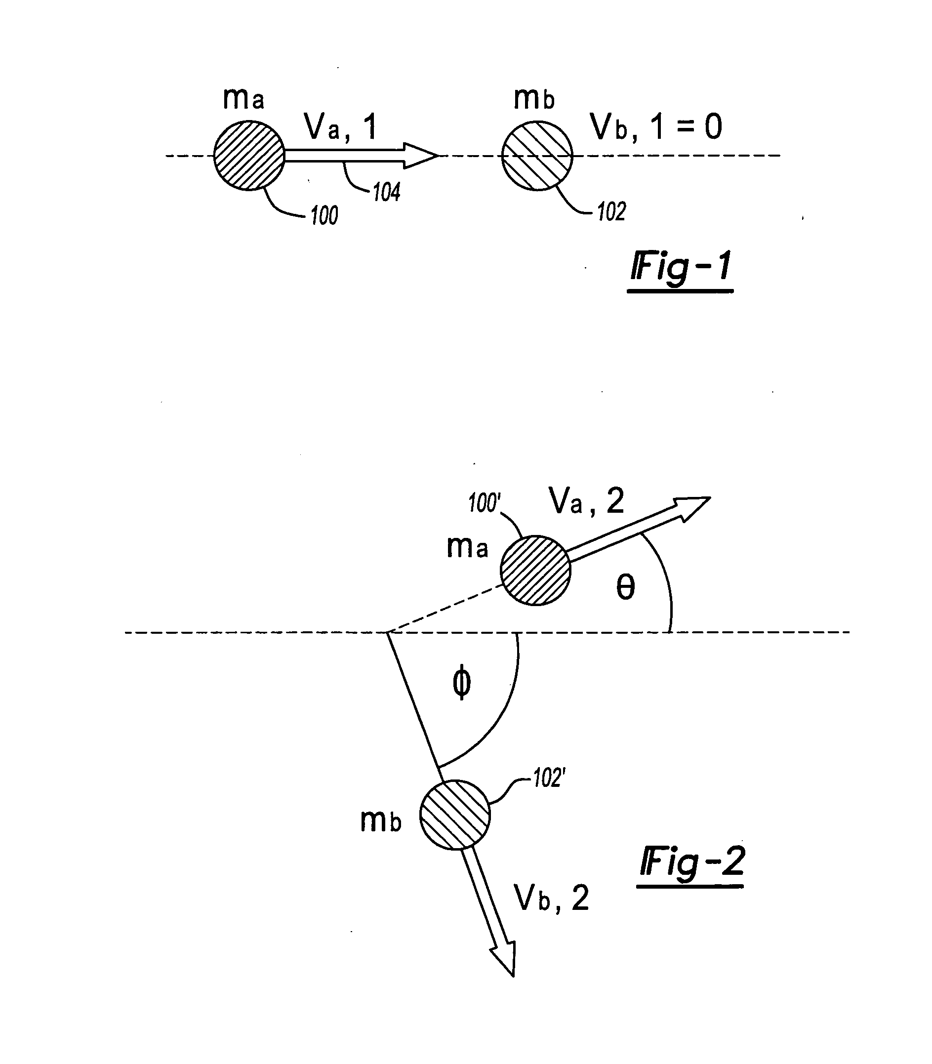
[0026]According to the principles of the present teachings, methods and systems are provided for identifying chemical composition of materials and, more particularly, for identifying chemical composition of materials through analysis of the energy and direction of elastically scattered neutrons. The principles of these teachings are predicated, at least in part, on the fundamental process of neutron elastic scattering (NES), which is set forth in detail in U.S. Pat. Nos. 4,864,142; 4,918,315; 5,142,153; and 5,440,136, which are incorporated herein by reference.

[0027]Briefly, by way of introduction, the principles of the present teachings provide that the speed of a neutron is directly related to its energy. Because neutrons emitted from sources, such as neutron generators and some accelerator targets, are of known, si...


PUM


Abstract

A neutron elastic scattering detector device for non-invasively detecting the presence of at least one predetermined element of an object of interest. The detector device comprises a neutron source that simultaneously outputs, at a creation time, a neutron in a first direction and an associated baseline particle in a second direction. The first direction is opposite of the second direction. The neutron can impinge upon the predetermined element of the object of interest and scatter therefrom in a third direction. A baseline particle detector system detects the baseline particle and outputs a baseline signal characteristic thereof. A neutron detector system detects the neutron and outputs a scattering signal in characteristic thereof. The processing unit analyzes the baseline signal and the scattering signal to determine the presence of the predetermined element.

Description

CROSS-REFERENCE TO RELATED APPLICATIONS[0001]This application claims the benefit of U.S. Provisional Application No. 60 / 654,845, filed on Feb. 18, 2005. The disclosure of the above application is incorporated herein by reference.FIELD[0002]The present disclosure relates to methods and systems for identifying chemical composition of materials and, more particularly, relates to methods and systems for identifying chemical composition of materials through analysis of the energy and direction of elastically scattered neutrons.BACKGROUND AND SUMMARY[0003]The statements in this section merely provide background information related to the present disclosure and may not constitute prior art.[0004]Recently, there has been an increasing need to permit the quick, non-invasive, non-destructive analysis of the chemical compositions of materials, especially when such materials are concealed, such as illicit materials or explosives, or otherwise spaced a considerable distance from the detection sy...

Claims


Application Information

Patent Timeline
IPC IPC(8): G01N23/00
CPCG01V5/0025G01T3/00
Inventor KEARFOTT, KIMBERLEE JANE
Owner RGT UNIV OF MICHIGAN
Why Eureka
Try Eureka