Catheter with embedded components and method of its manufacture

a technology of embedded components and catheters, applied in the field of catheters, can solve the problems of reducing the efficacy of electrophysiology catheters, affecting the mechanical stability of catheters, so as to improve the mechanical stability and mechanical stability, improve the stiffness of catheters, and improve the ability to retain mechanical properties

Inactive Publication Date: 2008-07-03
ST JUDE MEDICAL ATRIAL FIBRILLATION DIV
View PDF16 Cites 66 Cited by
  • Summary
  • Abstract
  • Description
  • Claims
  • Application Information

AI Technical Summary

Benefits of technology

[0022]An advantage of the present invention is that the embedded components reduce the need for a hollow shaft, thereby permitting a thicker wall and improving the catheter's hoop stiffness, which is often desirable when inserting the catheter into a patient's vasculature.
[0023]Another advantage of the present invention, particularly in connection with deflectable catheters, is an improved ability to retain mechanical and electrical integrity over multiple deflection cycles.
[0024]Still another advantage of the present invention is that, by embedding the internal components, the likelihood of fluid ingress is greatly reduced.
[0025]Yet another advantage of the present invention is that, by embedding the internal components, the amount of electrical noise is reduced.

Problems solved by technology

This is commonly referred to as “fluid ingress,” and is known to cause electrical noise on ECGs and shorts between electrodes.
Over several deflections, lead wires may become tangled, break, or lose their insulative coating as they rub against each other and the wall of the catheter shaft.
This, in turn, may lead to reduced efficacy of the electrophysiology catheter.
It is thus necessary to reduce the wall thickness of the catheter shaft, which reduces the stiffness of the shaft, potentially leading to undesirable flexure of the distal end during insertion into the patient's vasculature.

Method used


Image

  • Catheter with embedded components and method of its manufacture
  • Catheter with embedded components and method of its manufacture
  • Catheter with embedded components and method of its manufacture

Examples


Embodiment Construction

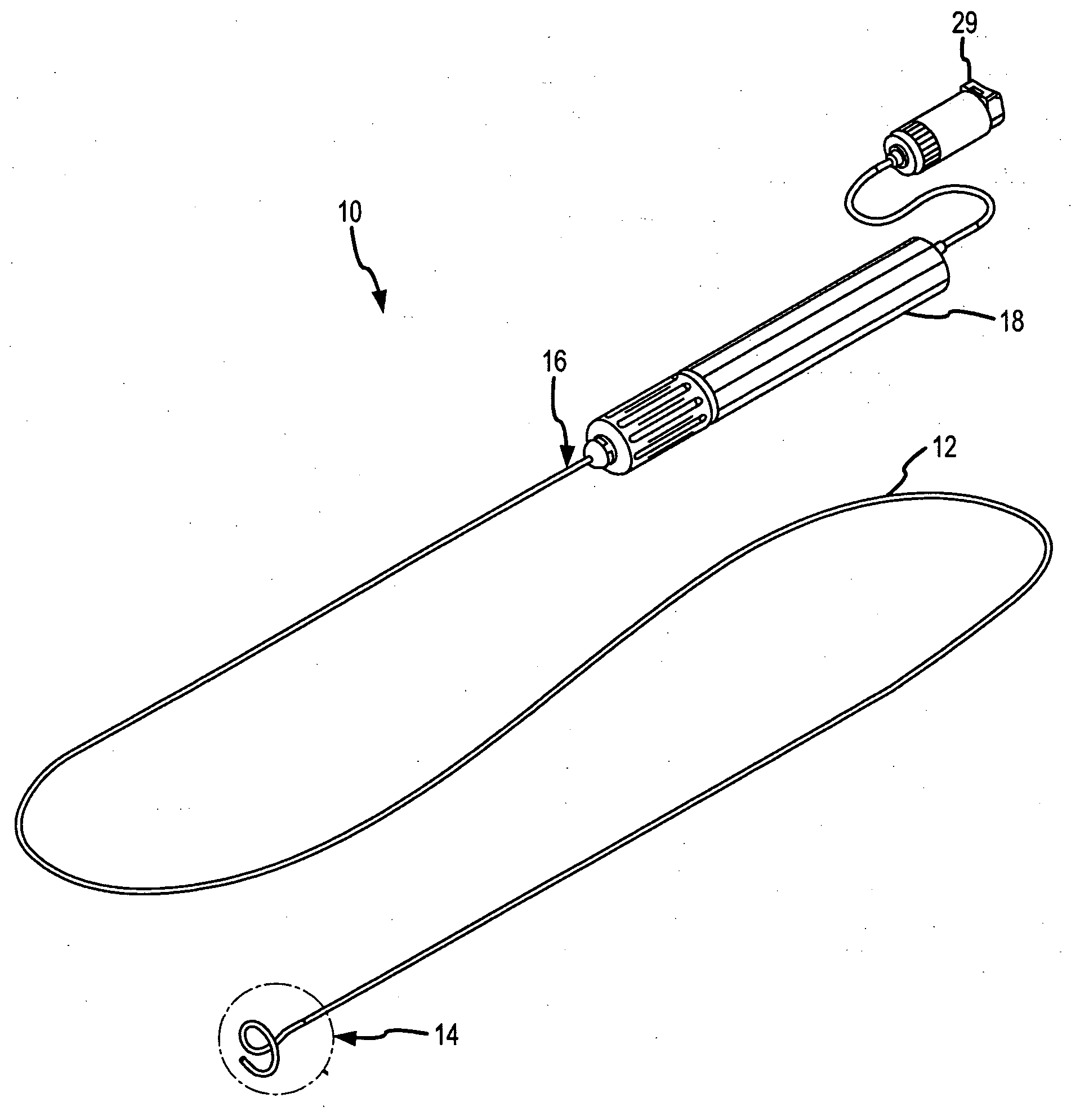
[0037]The present invention provides a catheter having internally embedded components and methods of manufacturing the same. For purposes of description, the present invention will be described and illustrated in connection with a spiral mapping catheter, such as the Livewire Spiral HP™ catheters of St. Jude Medical, Inc. It is contemplated, however, that the described features and methods may be incorporated into any number of catheters, as would be appreciated by one of ordinary skill in the art.

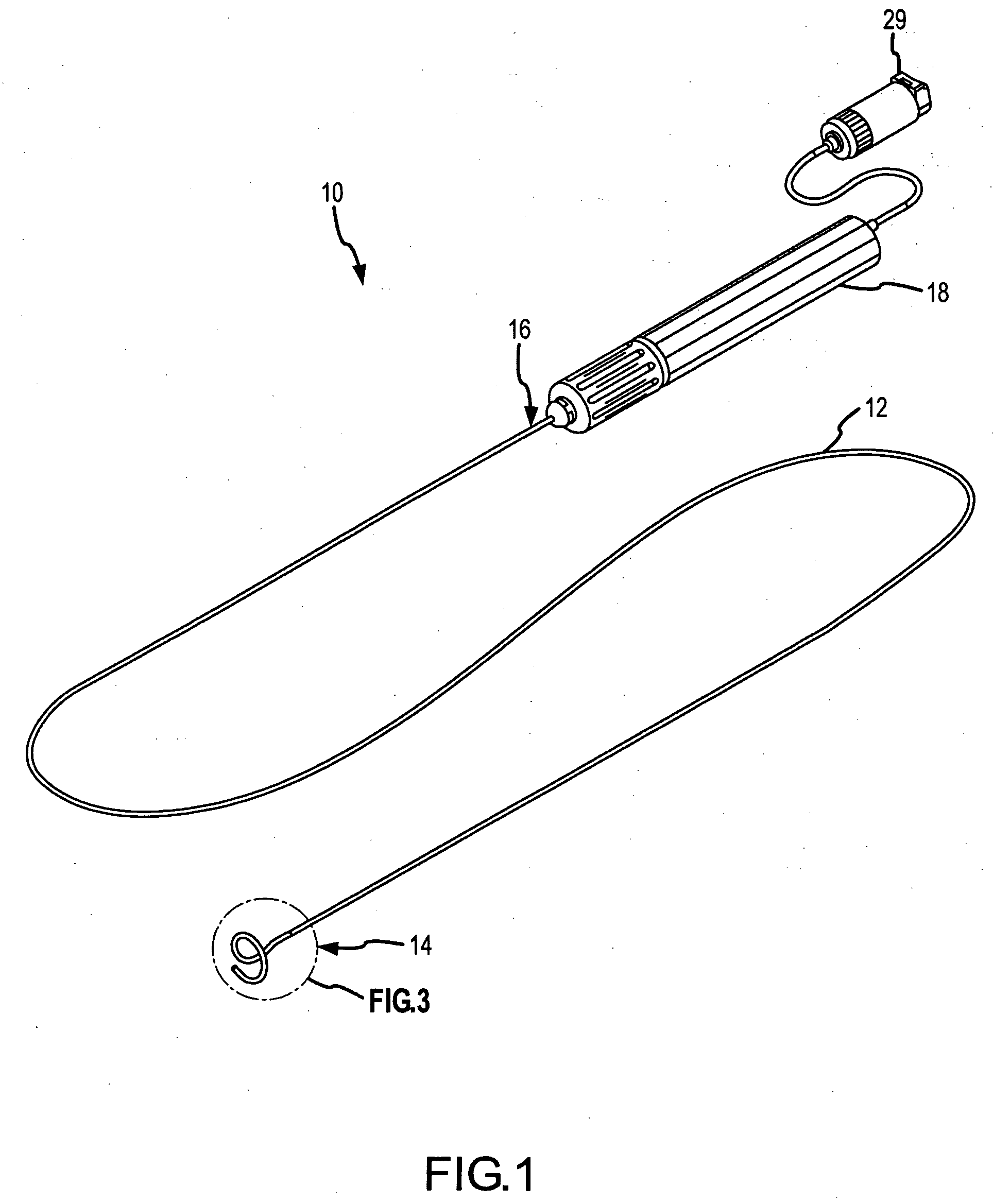
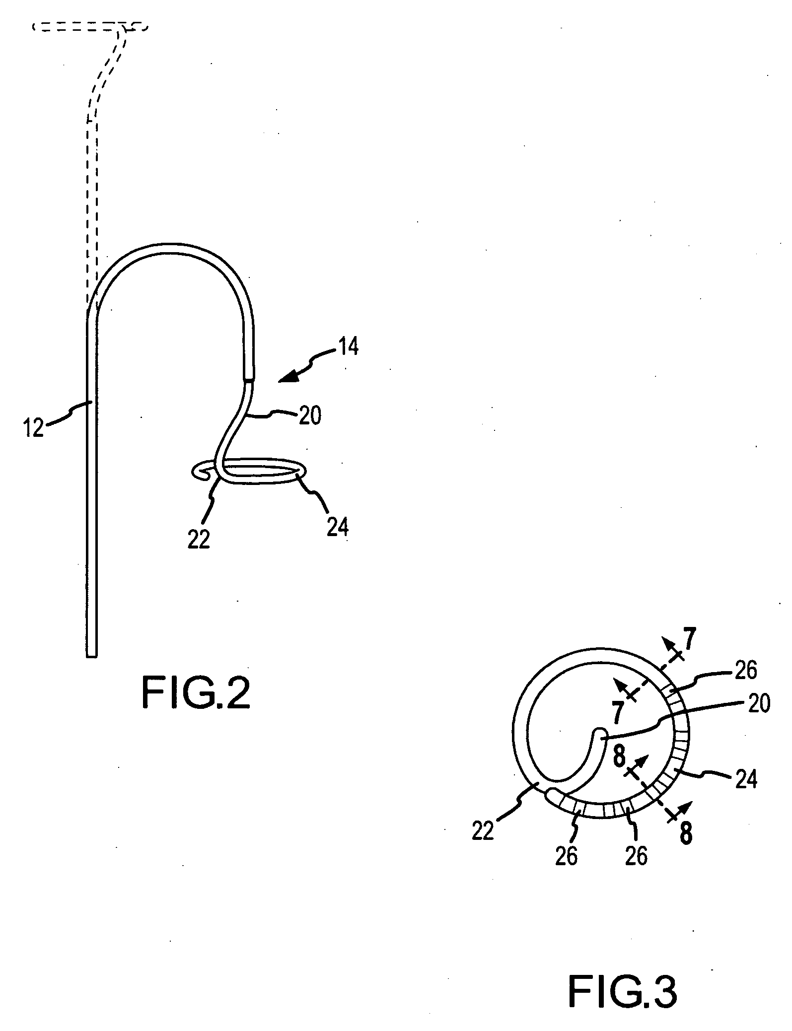
[0038]Referring now to the figures, and in particular to FIG. 1, an electrophysiology catheter 10 includes a shaft 12 having a distal end 14 and a proximal end 16. A handle 18 may be coupled to proximal end 16 of shaft 12 to control catheter 10.

[0039]As best shown in FIG. 2, shaft 12 may be deflected from a generally straight configuration, shown in phantom, into one or more curved configurations. Deflectability may be provided by one or more steering wires or pull wires (not shown) extend...


PUM

PropertyMeasurementUnit
energyaaaaaaaaaa
thermal energyaaaaaaaaaa
radio frequency energyaaaaaaaaaa

Abstract

A method of manufacturing a catheter includes providing an outer shaft having a lumen therethrough and at least one catheter component disposed at least partially within the lumen, placing an inner shaft within the lumen such that the at least one catheter component is located between the shafts, thereby forming a catheter assembly having an outer surface, and applying energy to the catheter assembly to melt at least the outer shaft to bond the outer shaft to the inner shaft. A unitary catheter shaft having the at least one catheter component substantially embedded therein results. The durometer of the outer shaft may differ from the durometer of the inner shaft, such that the catheter shaft varies radially in durometer. The durometer of the catheter shaft may also vary longitudinally. A shaping wire may be provided to form the distal end of the catheter shaft into a desired shape.

Description

BACKGROUND OF THE INVENTION[0001]a. Field of the Invention[0002]The instant invention relates to catheters that are used in the human body. In particular, the instant invention relates to a catheter with embedded internal components. The present invention also relates to methods of manufacturing a catheter with embedded internal components.[0003]b. Background Art[0004]Catheters are used for an ever-growing number of procedures. For example, catheters are used for diagnostic, therapeutic, and ablative procedures, to name just a few examples. Typically, the catheter is manipulated through the patient's vasculature and to the intended site, for example a site within the patient's heart.[0005]A typical electrophysiology catheter includes an elongate shaft. The shaft includes one or more lumens therethrough. The catheter's internal components will generally be disposed within the lumens and / or routed to the proximal end of the catheter through the lumens. For example, a pull wire to defl...

Claims


Application Information

Patent Timeline
Patent Type & Authority Applications(United States)
IPC IPC(8): A61M25/16
CPCA61B5/0422A61M25/005A61B18/1492A61B5/6857A61B5/287
Inventor HASTINGS, JOHN M.KING, ALICIA A.
Owner ST JUDE MEDICAL ATRIAL FIBRILLATION DIV
Why Eureka
Try Eureka