Pulse oscillating type solid laser unit and laser process unit

a laser unit and laser technology, applied in semiconductor lasers, active medium materials, manufacturing tools, etc., can solve the problems of difficult placement of the laser unit body, difficult to predict the actual output of the laser output accurately from the laser output for monitoring, and follow defects, so as to reduce processing costs and reduce processing costs. , the effect of reducing the yield ratio

Inactive Publication Date: 2008-07-10
KATAOKA
View PDF3 Cites 2 Cited by
  • Summary
  • Abstract
  • Description
  • Claims
  • Application Information

AI Technical Summary

Benefits of technology

[0021]In order to solve the above problems, the present claimed invention provides an art that can change a closed loop control system of LD current wherein monitor laser output is a feedback signal to an open loop control system wherein an LD current value corresponding to a laser output value is conducted in a simple manner.
[0023]In accordance with the arrangement, since an art of conducting the pulse LD current value to obtain a desired pulse laser output value can be established, it is possible to obtain a stable laser output value all the time. As a result, for the laser process unit using the laser unit body, since processing defect such as accuracy defect or strength defect originating in excess or deficiency of laser output decreases, a yield ratio of a processing improves and a processing cost is lowered. Further, processing material resources can be economized and a running cost can be reduced, thereby to provide a more global environment friendly laser process unit.
[0028]By applying a monitor art of the monitor light output in accordance with the present claimed invention it is possible to measure the pulse laser output value and to detect an error laser output in a msec order, in spite of a short term oscillating operation or even though a pulse repetition frequency is not greater than 100 Hz.
[0029]As a result of this, for a laser processing using the laser process unit, since processing defect such as accuracy defect or strength defect originating in excess or deficiency of laser output decreases drastically, a yield ratio of a processing improves and a processing cost is lowered. Further, processing material resources can be economized and a running cost can be reduced, thereby to provide a more global environment friendly laser process unit.

Problems solved by technology

However, a conventional arrangement wherein a PIN type Si photo diode is used as a high speed power sensor of laser light for monitoring has following defects.
However, a power split rate and a power attenuating rate of an optical component used as the high-precision power split means and the high attenuating means are easily changed in its characteristics due to humidity change or dust adhered to the optical component, which makes it difficult to predict actual Nd:YAG laser output accurately from the laser output for monitoring.
Then it is difficult for the laser unit body placed under an environment wherein ambient temperature is not constant to predict actual Nd:YAG laser light output with accuracy in a stale manner from the measured laser output for monitoring.
As a result of this, the Nd:YAG laser unit wherein the laser output value for monitoring measured by the high speed power sensor is controlled as a feedback signal could not obtain stable Nd:YAG laser output with absolute precision of not greater than 2% due to the above-mentioned problems of the high power sensor.
Then a problem was developed that processing defect such as accuracy defect or strength defect was inevitable for a laser processing using the laser unit body of the above-mentioned arrangement.
As a result, when the laser output drops drastically due to damage of the total reflection mirror 105 and the output bond mirror 106 constituting the laser resonator 104 because of dust or dirt attached thereto, a problem is developed such as a processing is continued without a normal laser processing because detection of an error state such as output drop is delayed or the detection is impossible.

Method used


Image

  • Pulse oscillating type solid laser unit and laser process unit
  • Pulse oscillating type solid laser unit and laser process unit
  • Pulse oscillating type solid laser unit and laser process unit

Examples


Embodiment Construction

[0041]The invention will be described in detail with reference to an embodiment thereof shown in the accompanying drawings.

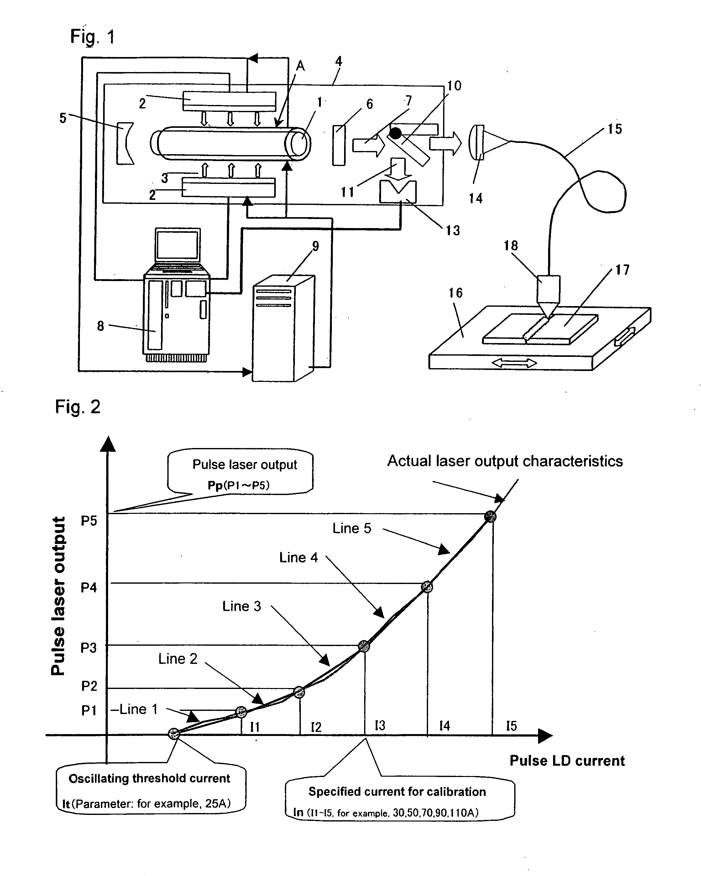
[0042]As one embodiment of the present claimed invention, FIG. 1 shows an arrangement of a solid laser unit whose primary purpose is a laser welding processing and mainly comprising an LD excited pulse type Nd:YAG laser unit body A wherein a laser activated media is rod-type Nd:YAG crystal 1 and a mean output is in a 300 W class.

[0043]The Nd:YAG crystal 1 whose rod diameter is 5 mm and whose length is 116 mm is excited by LD light 3 radiated from an LD excited unit 2 equipped with 60 bars of 20 W / bar LDs oscillating at a central wavelength of 808 nm, light of 1.06 μm irradiated from the Nd:YAG crystal 1 is selectively amplified between a total reflection mirror 5 and an output bond mirror 6 whose reflection coefficient is 70%, each of the mirrors 5, 6 constituting a laser resonator 4 whose resonator length is 400 mm, so as to be Nd:YAG laser light 7 and then the...


PUM

PropertyMeasurementUnit
lengthaaaaaaaaaa
lengthaaaaaaaaaa
diameteraaaaaaaaaa

Abstract

A pulse oscillating type solid laser unit that has a laser unit body whose exciting source is a laser diode that emits light in a principal energy absorbing spectrum of a solid laser activated media, and characterized by that prior to radiating laser light outside the laser unit body as a calibrating operation of a pulse laser output value, specified several varieties of rectangle pulse current values are conducted to a laser diode inside the pulse oscillating type solid laser unit so as to pulse-oscillate the laser unit body, a mean laser output value in each rectangle pulse current value is measured by the use of a laser output measuring instrument arranged inside the laser unit body so as to obtain a mean laser output value data, and in case that the laser output light is radiated outside the laser unit body, a pulse current value linear-predicted based on an obtained mean output value data is conducted to the laser diode so as to obtain a desired pulse laser output value.

Description

CROSS-REFERENCE TO RELATED APPLICATIONS[0001]This application is a Divisional of U.S. patent application Ser. No. 10 / 492,366, filed Apr. 13, 2004, and wherein application Ser. No. 10 / 492,366 is a national stage application filed under 35 USC § 371 of International Application No. PCT / JP02 / 01390, filed Feb. 18, 2002, the entire disclosures of which are hereby incorporated by reference.FIELD OF THE ART[0002]This invention relates to a pulse oscillating type solid laser unit that preferably solves a problem of instability in a processing and a laser process unit that does not produce a processing defect due to fluctuation of a laser output.BACKGROUND ART[0003]Recent progress of a laser diode (hereinafter noted as an LD) excited solid laser unit body wherein its output and luminance are highly developed makes it possible for a laser unit to conduct a precise welding processing or a fine removal processing with high speed and high precision that used to be impossible for a conventional p...

Claims


Application Information

Patent Timeline
Patent Type & Authority Applications(United States)
IPC IPC(8): H01S3/13B23K26/00H01S3/00H01S3/0941H01S3/131H01S3/16H01S5/042H01S5/06H01S5/0683
CPCB23K26/0639B23K26/0853B23K26/24B23K26/422H01S3/0941H01S5/0683H01S3/1312H01S3/1643H01S5/0428H01S5/0617H01S3/10069B23K26/064B23K26/702H01S3/10B23K26/0622
Inventor IEHISA, NOBUAKI
Owner KATAOKA
Why Eureka
Try Eureka