
Integrated Sample Collector And Tester For Bodily Fluid

a sample collector and bodily fluid technology, applied in the field of bodily fluid testers, can solve the problems of destroying the value of the test, the test procedure is relatively complex, etc., and achieves the effects of reducing the manufacturing cost of the test kit, improving ease and reliability of use, and facilitating manufacturing

Inactive Publication Date: 2008-07-10
STATURE DIAGNOSTIC SYST
View PDF9 Cites 3 Cited by
  • Summary
  • Abstract
  • Description
  • Claims
  • Application Information

AI Technical Summary

Benefits of technology

[0004]In accordance with one aspect of the present invention, the sample collector and test strip of a testing kit are integrated into a single inexpensive element, which is easily manufactured, substantially reducing the manufacturing cost of the test kit. In addition, this results in the elimination of one of the steps in using the test kit, substantially improving ease and reliability of its use.
[0005]In accordance with another aspect of the invention, a test kit is provided with a test container including a pre-measured amount of buffer solution and an element integrating a sample collector and test strip. As a result, the user need merely collect the fluid sample with the integrated element and then drop it into the buffer solution. This eliminates another step from the test procedure, providing a further improvement in ease of use and reliability. In essence, the test procedure is reduced to acquiring the sample and dropping the integrated element into the buffer solution.
[0006]In accordance with yet another aspect of the invention, a plurality of integrated collector / test-strip elements can be formed efficiently on a single sheet of material, hereafter referred to a “card”, after which the card can simply be cut to divide it into individual elements. It is also contemplated that a card may be provided in pre-divided form on a backing sheet, from which individual collector / test-strip elements may be peeled for use.

Problems solved by technology

Unfortunately, the use of such a test kit presents a number of disadvantages.
Secondly, the test procedure is relatively complex, especially for a consumer.
With a distinct sequence of steps to be performed, the possibility exists that an error could be made at any one of the steps, destroying the value of the test.

Method used


Image

  • Integrated Sample Collector And Tester For Bodily Fluid
  • Integrated Sample Collector And Tester For Bodily Fluid
  • Integrated Sample Collector And Tester For Bodily Fluid

Examples


Embodiment Construction

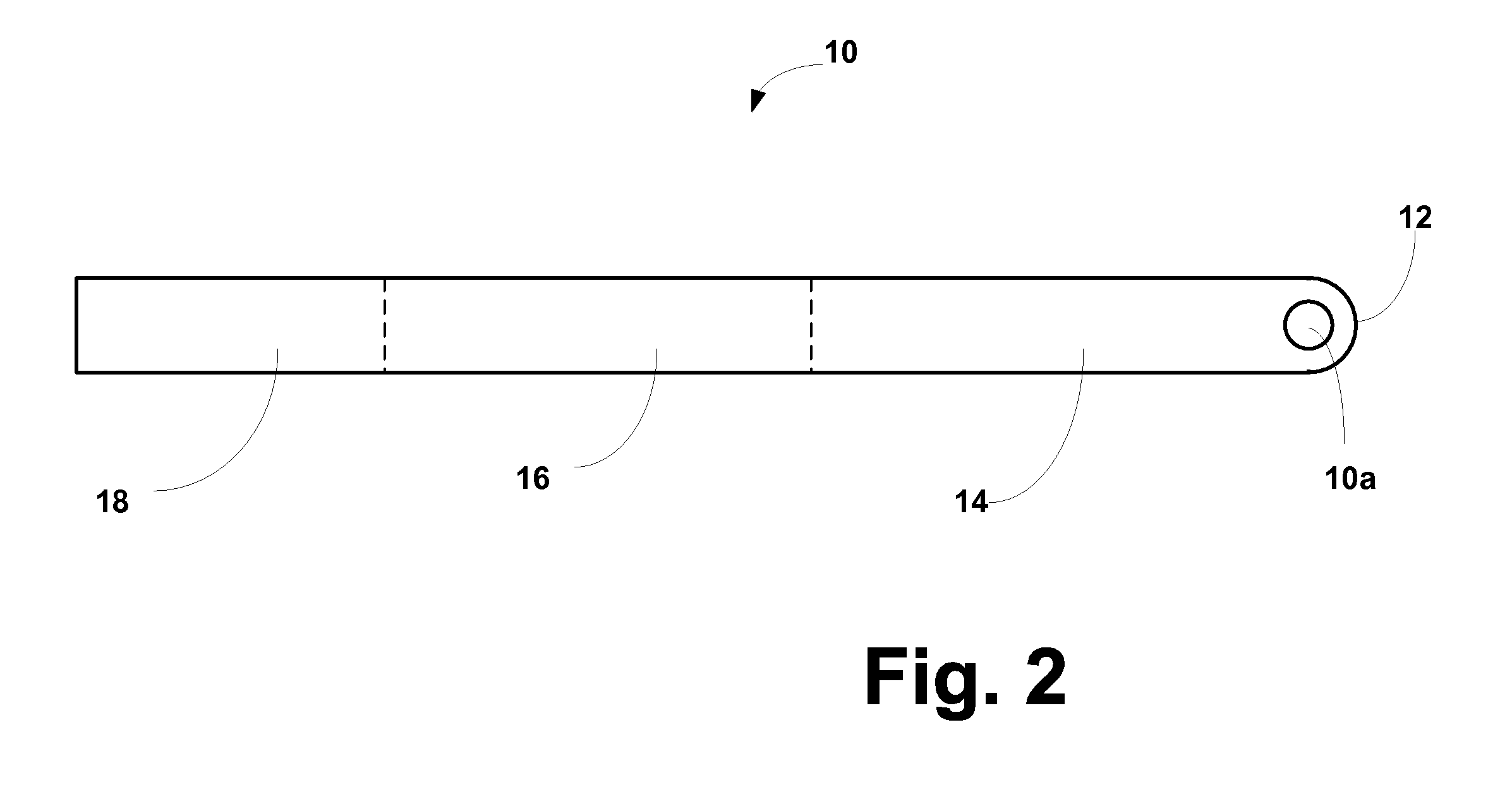
[0016]Turning now to the drawings, FIG. 2 is a plan view of the first embodiment 10 of an integrated collectors / test-strip element embodying the present invention, in this case, an element for use in blood testing. In this embodiment, element 10 is made of an elongate strip of plastic sheet material which is about 77 mm long and about 5 mm wide. At a first end 12, element 10 is provided with a through-hole 10a having about a 2 mm diameter. However, those skilled in the art will appreciate that the dimensions of element 10 and the diameter of hole 10a may be varied, as necessary for the particular application. In particular, the diameter of hole 10a may be varied to adjust the quantity of blood being collected.

[0017]A forward portion 14 of element 10, preferably about 30 mm in length, is surface treated so as to absorb test solution. Following portion 14, an intermediate portion 16, preferably about 25 mm in length, contains a nitrocelluloid membrane which is constructed to change ap...


PUM

PropertyMeasurementUnit
diameteraaaaaaaaaa
lengthaaaaaaaaaa
lengthaaaaaaaaaa

Abstract

In a testing kit for bodily fluids, a device is provided which combines a specimen collection component and a testing component, which are integrated into a single, inexpensive element that is readily manufactured. This permits testing by collecting a specimen with the device, then simply dropping it into a predetermined quantity of buffer solution.

Description

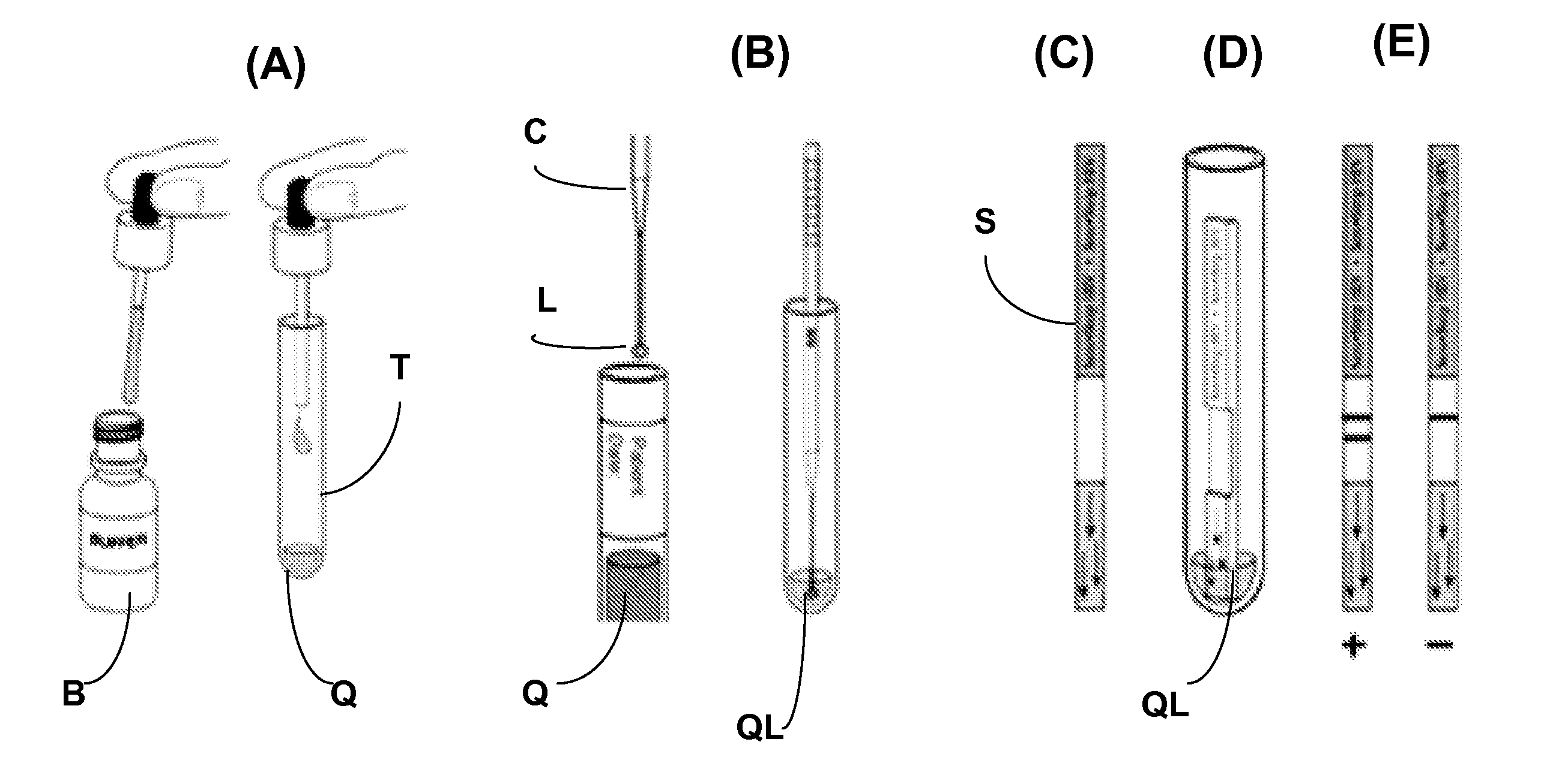
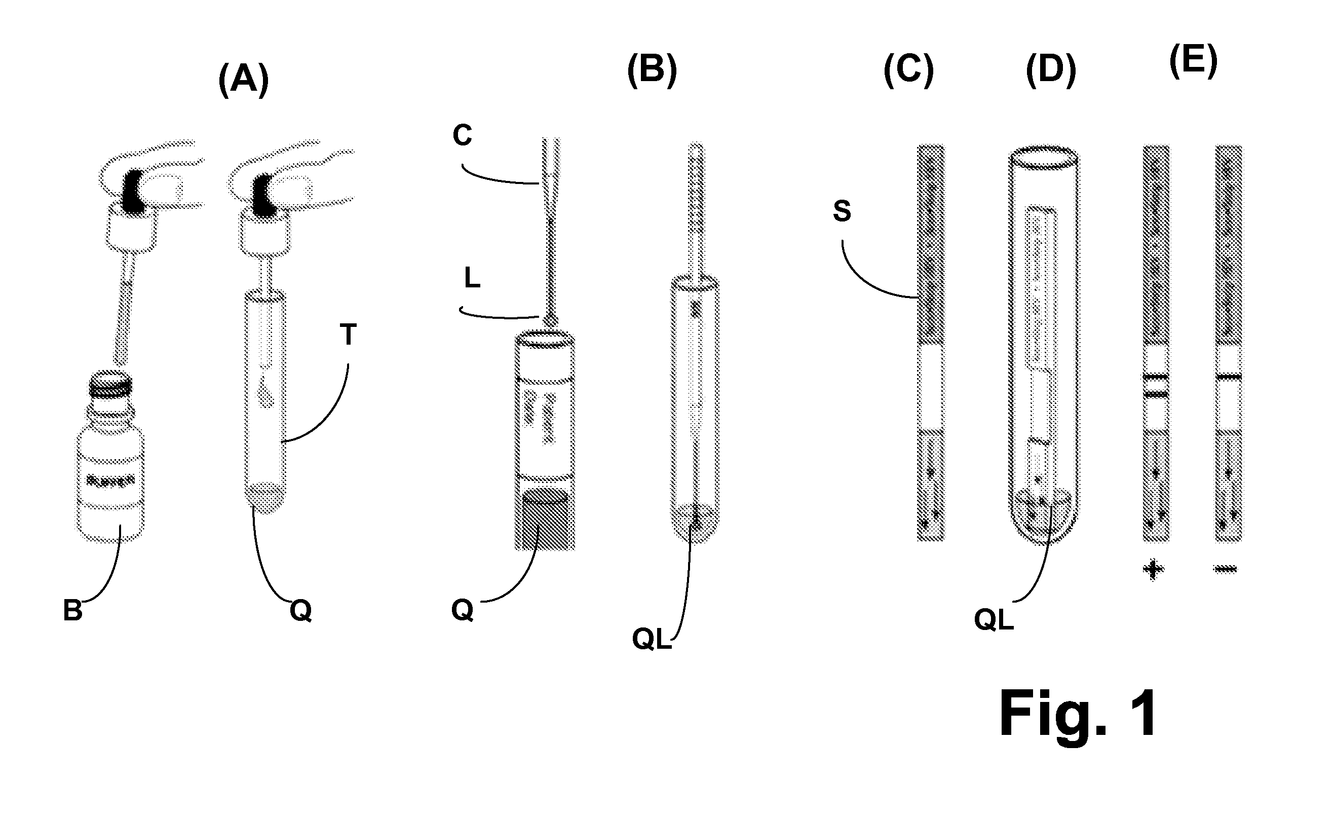
BACKGROUND OF THE INVENTION[0001]The present invention relates generally to testers for bodily fluids and, more particularly, concerns a device which combines a sample collector with a fluid test element, a method of manufacturing the device, and a method of using the device.[0002]Test kits for bodily fluids, including self-test kits, are widely available. For example, a typical blood testing kit includes (see FIG. 1) a test container T, a sample collector C, a dispensing bottle of sample buffer solution B. and a chemically treated test strip S. In use, the patient dispenses a measured quantity of the buffer solution Q into the test container (FIG. 1A); acquires a measured quantity of blood L from a punctured fingertip using the collector C, and deposits the blood L in the buffer solution Q, to create the test solution QL. Collector C. is then removed from container T, and a test strip S (FIG. 1C) is deposited into the test solution QL (FIG. 1D). Strip S has been chemically treated ...

Claims


Application Information

Patent Timeline
Patent Type & Authority Applications(United States)
IPC IPC(8): G01N21/77B01J19/00B23P17/00B32B3/10
CPCA61B10/0045A61B2010/0006Y10T29/49789B01L2300/0663Y10T428/24273B01L3/5029
Inventor ENNIS, JOHN
Owner STATURE DIAGNOSTIC SYST
Learn More