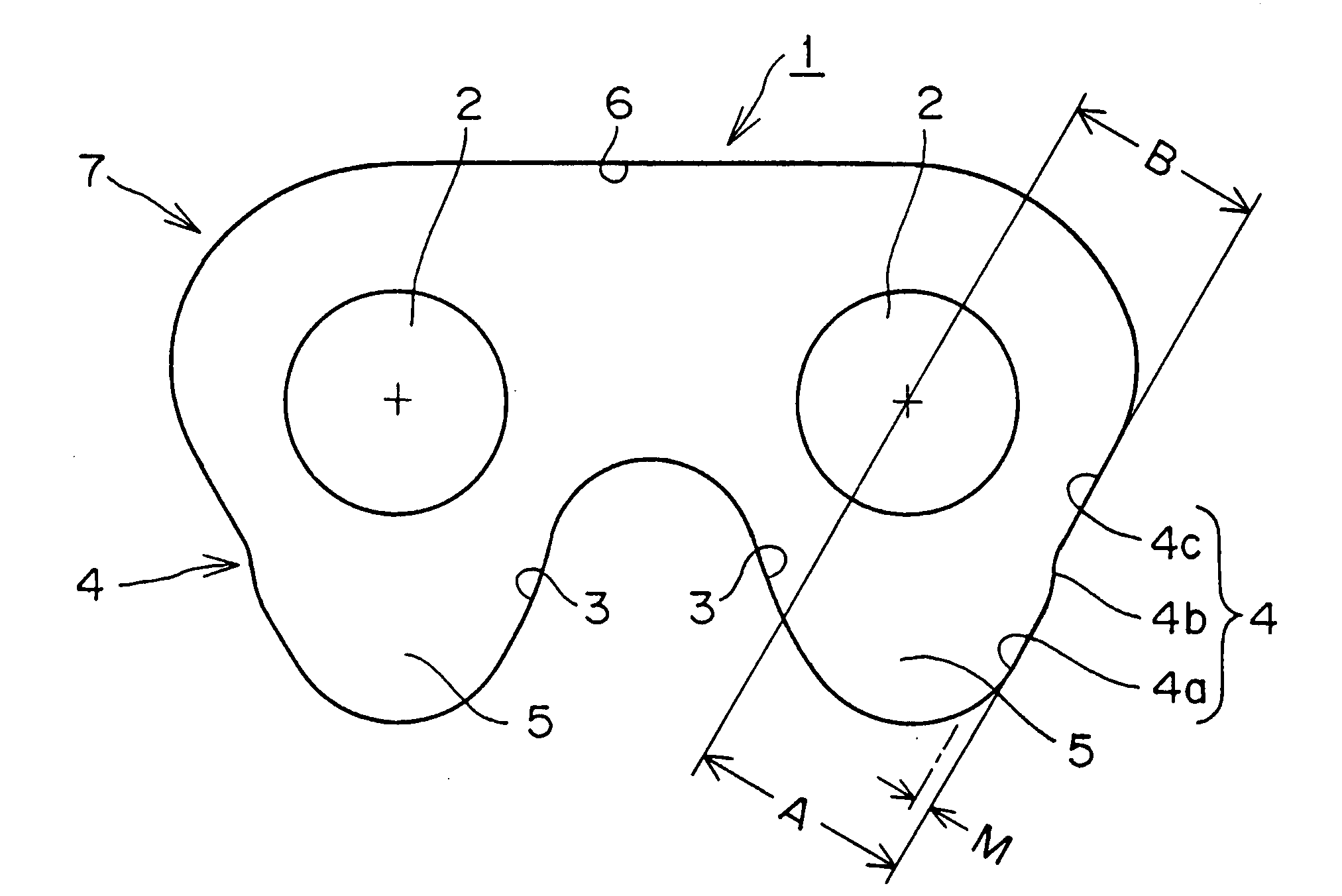
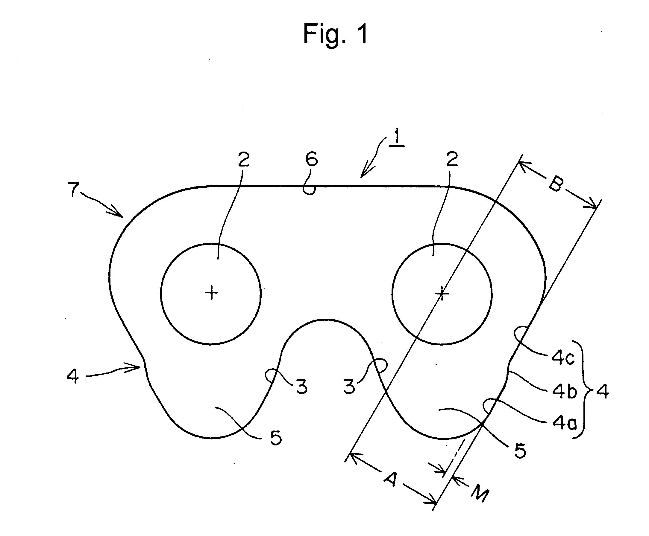
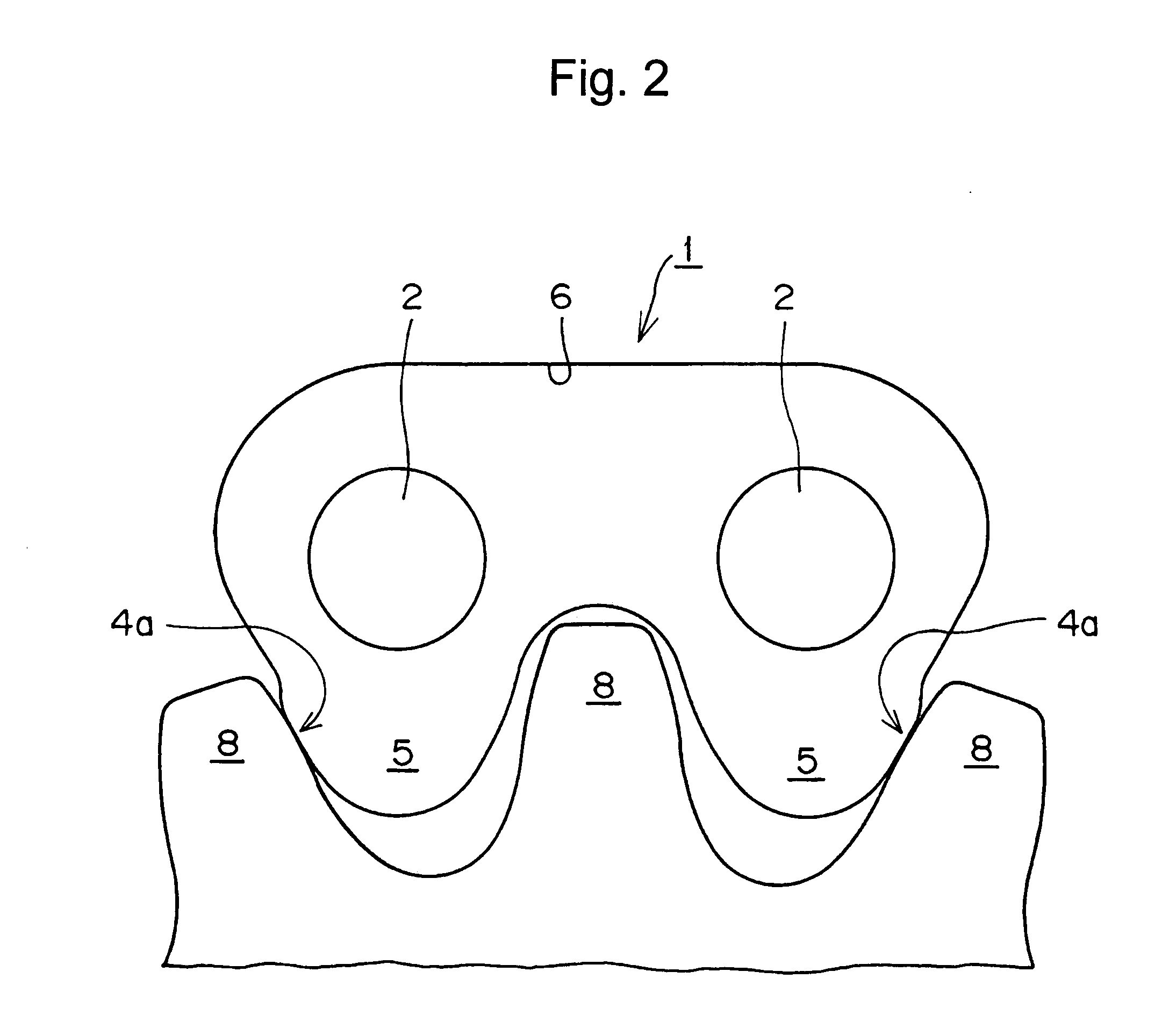
[0012]The link plate in accordance with the invention has a back, a pair of pin holes, and a pair of teeth. Each pin hole is adapted to receive a connecting pin for articulably connecting interleaved rows of link plates to form a chain. Each tooth of the link plate has a tip, an inner flank, and an outer flank. The outer flank extends from a shoulder adjacent the back of the link plate toward the tip of the tooth, and the outer flank comprises first and second parts connected to each other by a step. The first part is positioned farther than the second part from the back of the link plate, and protrudes relative to the second part. The first part comprises a first straight linear edge portion adapted to engage a sprocket tooth, and the second part also comprises a second straight linear edge portion. However, the second part is in a retracted position relative to the first part so that the second straight linear edge portion is prevented from coming into contact with a sprocket tooth.
[0014]The terms “shaving” and “shaved” as used herein refer to
processing for improving the shear plane coefficient and reducing roughness of an edge, such as an outer tooth flank, of a link plate by
cutting a
rough surface and a shear drop generated during
punching of the link plate. Shaving is carried out by means of a shaving tool that extends slightly beyond the edge of the punch used to punch a blank punched from a band of
sheet steel.
[0015]According to the invention, since the surface having a straight linear part for engagement with a sprocket tooth protrudes from a portion of the outer flank adjacent the tip of the tooth, and the surface having a linear, straight, portion which does not come into contact with the sprocket tooth is close to the shoulder of the link plate, and retracted relative to the shaved part, a portion of the link plate, which is not involved in engagement with a sprocket tooth, is not removed from the band of steel sheet during manufacture. Thus, a link plate can be formed economically, without needless use of steel.
[0016]Furthermore, since the protruding portion of the outer flank engages a sprocket tooth, whereas the retracted portion, positioned between the protruding portion and the shoulder of the link plate, does not come into contact with the sprocket, the shoulder of the link plate does not abut a sprocket tooth as the link plate is seating on the sprocket, and consequently, noises generated as the link plate is seating can be prevented.
[0017]When the protruding surface of the outer flank of the link plate is a shaved surface, and the retracted surface is a non-shaved surface, the non-shaved surface does not abut the sprocket tooth, but the shaved surface always comes into contact with a sprocket tooth. In this way, the engagement surface is stabilized so that engagement accuracy, fatigue strength, and desirable dynamic performance characteristics such as
wear resistance,
noise reduction, and the like, can be maintained.
[0018]Furthermore, since only the protruding surfaces are subjected to shaving, special measures to ensure accuracy during maintenance of the punches used to form the link plates are unnecessary. For the same reason, positioning shifts due to differences in steels used as the materials for the link plates, and position shifts due to variations in the accuracy of the punches, are less serious, and less labor is required for management of lots of
raw material and for maintaining manufacturing accuracy.

