Folded Surface Capacitor In-line Assembly

a capacitor and folding surface technology, applied in the field of compact coaxial inline capacitor assembly, can solve the problems of limited power rating of assemblies, significant impedance discontinuity, and high manufacturing cos

Active Publication Date: 2008-07-17
COMMSCOPE TECH LLC
View PDF44 Cites 37 Cited by
  • Summary
  • Abstract
  • Description
  • Claims
  • Application Information

AI Technical Summary

Benefits of technology

[0025]The inner conductor is provided in two inner conductor segments 7 with mating ends 9 separated by a dielectric spacer 11. The inventor has recognized that improvements to the capacitance value and power handling capacity of the in-line capacitor may be realized by increasing the surface area of the mating ends 9. The surface area may be increased with a reduced corresponding increase in the required overall length and or diameter of the resulting assembly, by forming the mating surface 15 with folds 13.
[0027]The diameter of the mating surface 15, number of folds 13 and the depth of each fold 13 may each be adjusted to arrive at the desired surface area. For example, while FIGS. 1a-c demonstrate a plurality of concentric circular corrugations, FIGS. 2a-b demonstrate a single concentric corrugation and a peripheral lip of the corrugation depth. Compared to the prior planar inline capacitors, the reduced outer diameter of the mating surface 15 enabled by the mating surface 15 folds 13 enables, for an equivalent surface area, the surrounding outer conductor and or housing 21 to be formed with a smaller diameter, for example equal or close to that of the interconnecting coaxial cable, minimizing the introduction of impedance discontinuities to the assembly. Further, the outer periphery of the mating surface 15, and thereby the dielectric spacer 11 may be formed as a circle to reduce the generation of impedance discontinuities with respect to a circular inner conductor.
[0028]The mating surface 15 folds 13 also provide a significant improvement over a planar mating surface in that the mating surface 15 folds 13 provide a lateral movement interlock between the inner conductor mating surfaces, reducing the necessary dimensions of supporting structures such as insulators 23 between the inner conductor and the enclosing outer conductor or housing 21.
[0032]Prior cylindrical and or parallel plate mating surface in-line capacitors typically applied a plastic or polymer such as mylar or polytetrafluoroethylene (PTFE) as the dielectric spacer 11 material. Although these materials may be applied in an in-line capacitor according to the invention to minimize cost, the inventor has recognized that a significant increase in power capacity may be achieved if the dielectric spacer 11 is formed out of a ceramic dielectric material. The thermal properties of ceramic dielectric improve power handling, allowing a higher maximum operating temperature. Another advantageous property of a ceramic dielectric spacer 11 is that the ceramic material is resistant to compression and or thermal deformation. Thereby, the desired gap between the mating surfaces, the selected thickness of the dielectric spacer 11, may be maintained with a higher level of precision. Additionally, ceramic material has a higher voltage breakdown for a given thickness, thus reducing the potential for arc thru failure of the capacitor.
[0037]One skilled in the art will recognize that an in-line capacitor according to the invention represents significant improvements over the prior art, the improvements potentially including increased power handling capability, increased capacitance, lateral and or rotational inner conductor interlocking, reduction of impedance discontinuities, reduction of overall assembly materials requirements, reduction of overall assembly weight and reduction of overall assembly dimensions.Table of Parts1connection interface3second end5first end7inner conductor segment9mating end11dielectric spacer13fold15mating surface17front19back21housing23insulator27surge element29mating portion31swaged interconnection33shoulder

Problems solved by technology

The resulting assemblies have limited power ratings, are fragile, expensive to manufacture and introduce a significant impedance discontinuity to the associated coaxial line.
In particular, the adhesives SMD capacitors rely on to maintain their position on the center conductor can soften and shift due to high operating temperatures generated by the RF power passing through the device.
Any shift in position can permanently adversely affect the designed capacitance.
The resulting modules make tradeoffs between power handling capability, impedance discontinuity and size.
Further, these solutions require significant supporting structure to maintain the alignment of the inner conductor mating surfaces.

Method used


Image

  • Folded Surface Capacitor In-line Assembly
  • Folded Surface Capacitor In-line Assembly
  • Folded Surface Capacitor In-line Assembly

Examples


Embodiment Construction

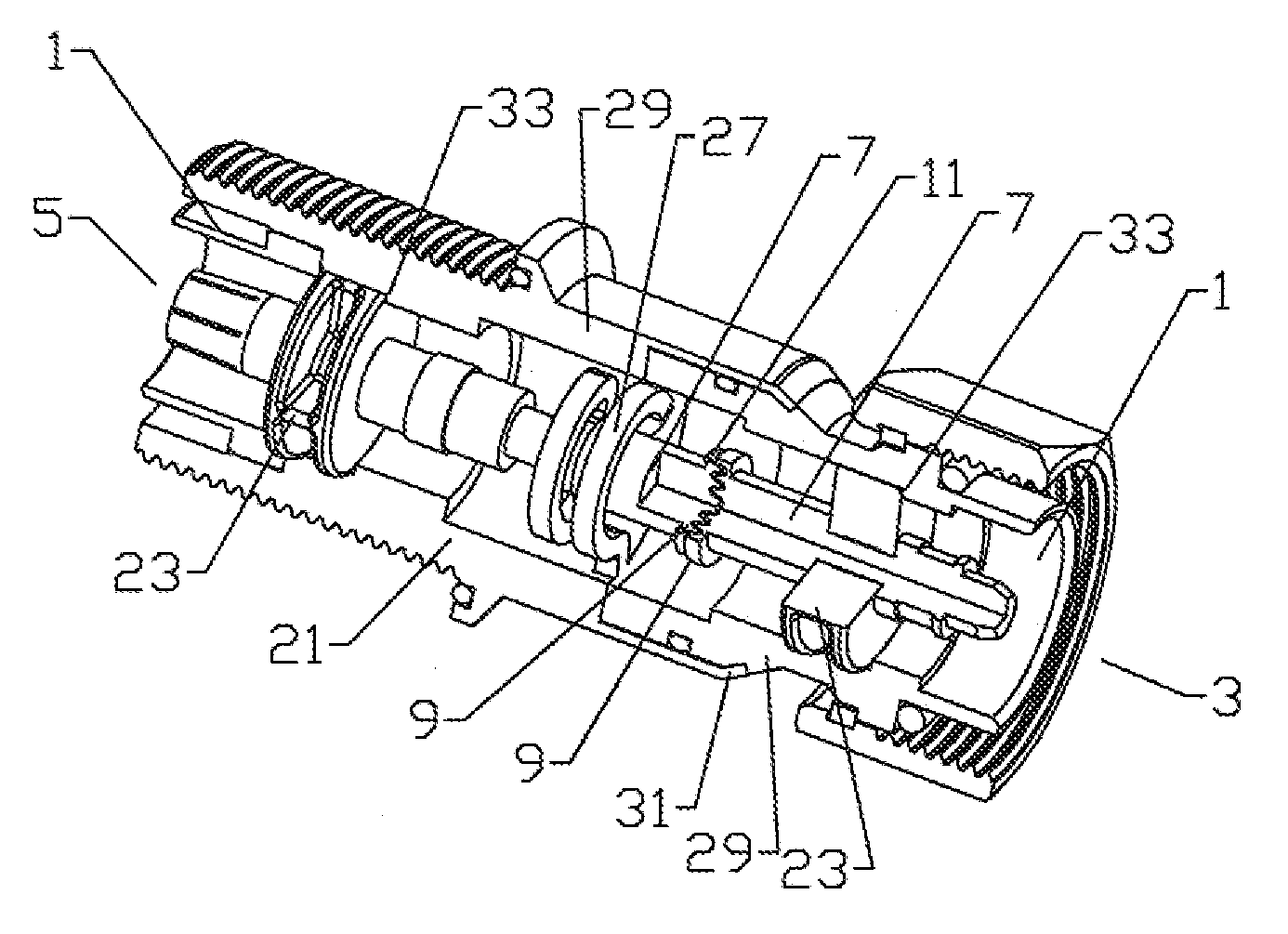
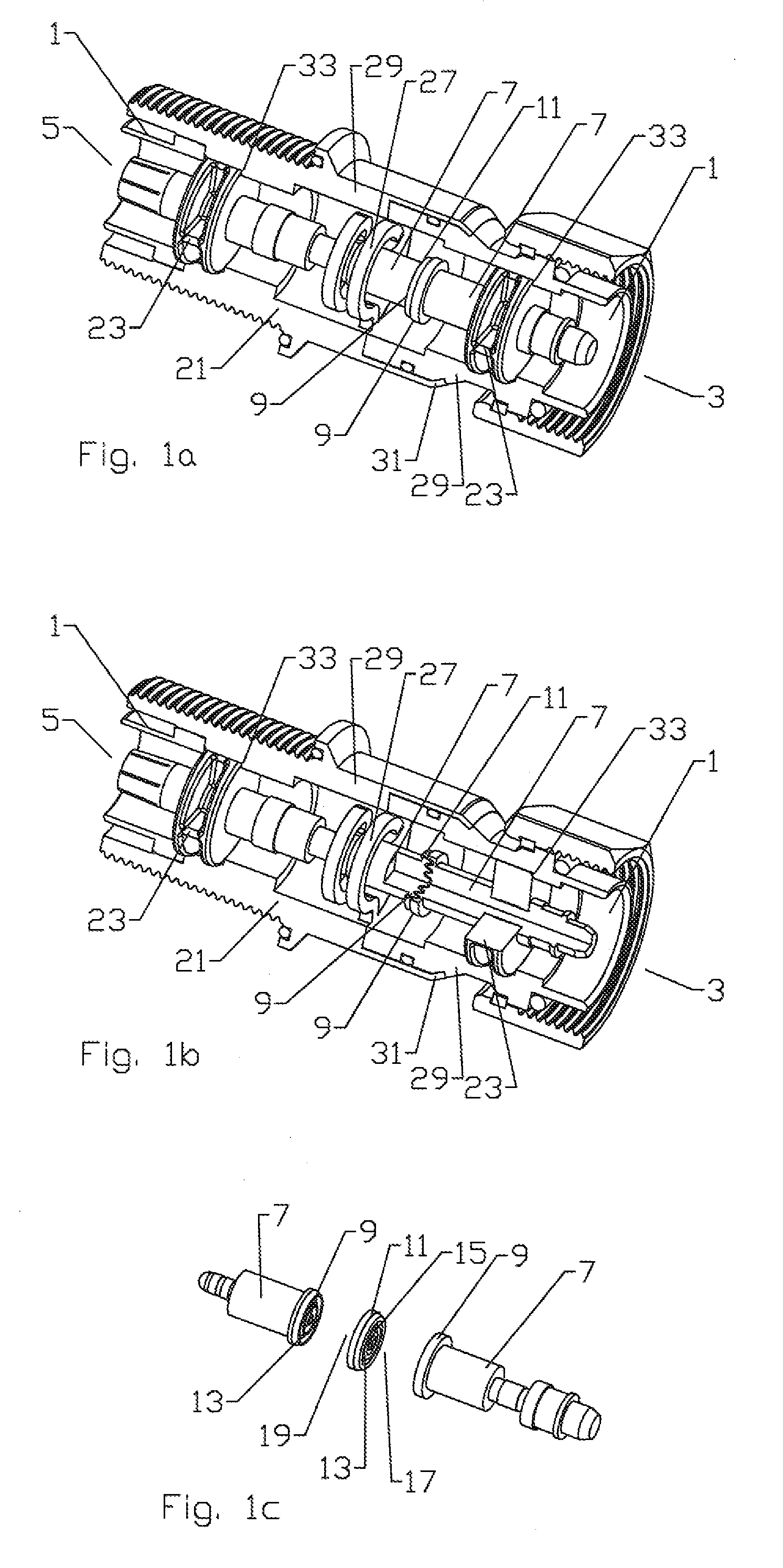
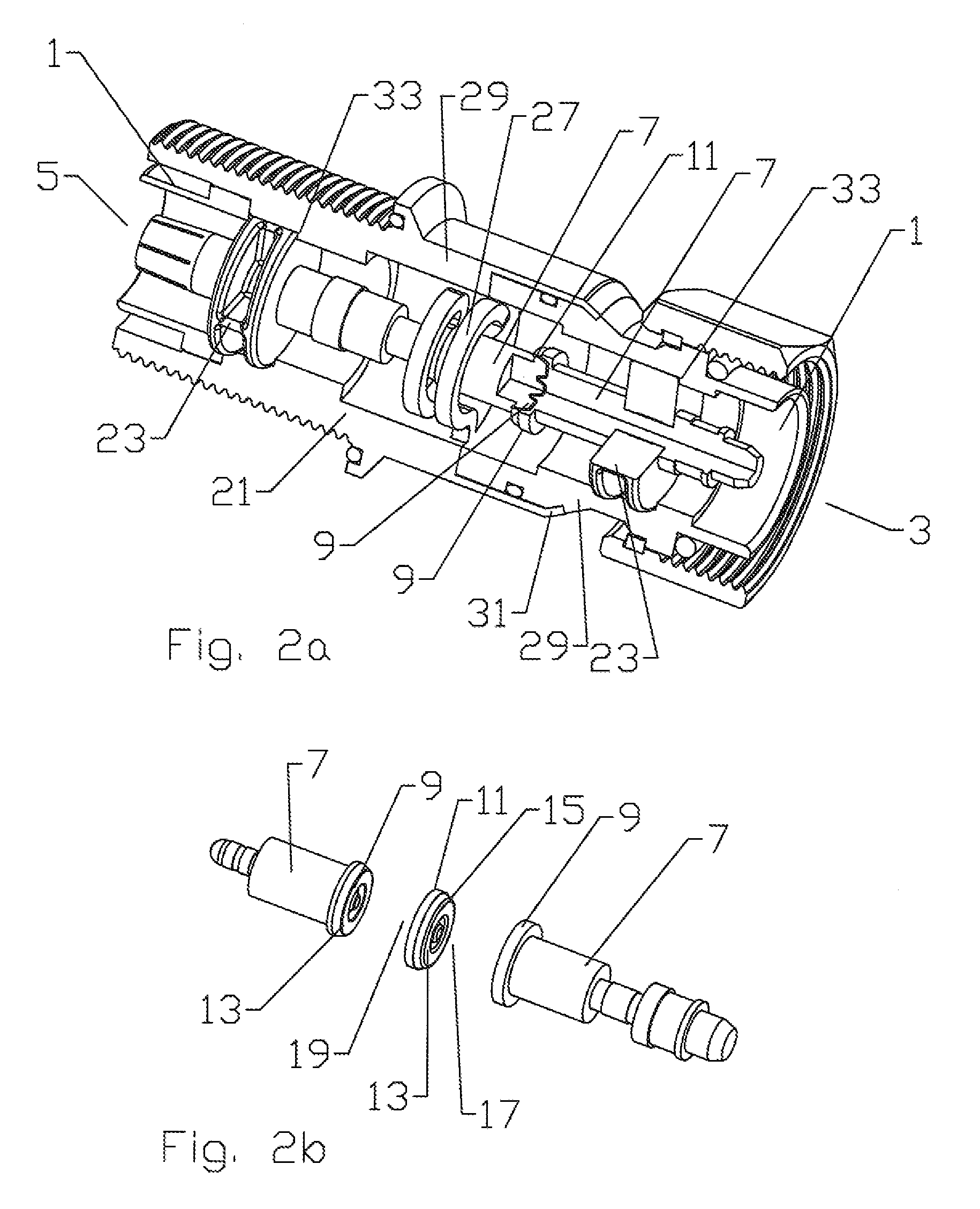
[0024]Exemplary embodiments of an in-line capacitor assembly are shown in FIGS. 1a-6b, for demonstration purposes, the in-line capacitor assembly is demonstrated as a surge suppressor for in-line connection via standardized male and female connection interfaces 1 at first and second ends of the housing 5, 3. One skilled in the art will recognize that the in-line capacitor assembly may easily be alternatively configured with additional and or alternative elements for a wide range of different purposes, such as DC-block, DC-bias, bandpass and or interference filtering or the like with any desired standardized or proprietary connection interface(s), including a coaxial cable direct connection interface.

[0025]The inner conductor is provided in two inner conductor segments 7 with mating ends 9 separated by a dielectric spacer 11. The inventor has recognized that improvements to the capacitance value and power handling capacity of the in-line capacitor may be realized by increasing the su...


PUM

PropertyMeasurementUnit
thicknessaaaaaaaaaa
depthaaaaaaaaaa
dimensionaaaaaaaaaa

Abstract

An in-line capacitor, having a pair of inner conductor segments, each of the inner conductor segments having a mating surface. A dielectric spacer positioned between the mating surfaces, each of the mating surfaces having corresponding folds formed thereon.

Description

BACKGROUND[0001]1. Field of the Invention[0002]The invention generally relates to inline capacitors. More particularly, the invention relates to a compact coaxial in-line capacitor assembly.[0003]2. Description of Related Art[0004]Electrical cables, for example the coaxial transmission lines interconnecting transceiver equipment with antenna towers, are equipped with surge suppression equipment to provide an electrical path to ground for diversion of electrical current surges resulting from, for example, static discharge and or lightning strikes.[0005]In-line surge suppression assemblies typically incorporate a frequency selective shorting element such as an inductive coil or stub between the inner and outer conductors of a coaxial cable. To prevent lower frequency and or direct current from being passed to down line equipment a physical break is inserted in the form of an in-line capacitor. The high frequency capacitive coupling across the capacitor is configured to pass only the d...

Claims


Application Information

Patent Timeline
Patent Type & Authority Applications(United States)
IPC IPC(8): H01C7/12H01G9/00H01G4/35H01G4/40H03H7/01
CPCH01G4/01Y10T29/417H01G4/12H01G4/06
Inventor VAN SWEARINGEN, KENDRICK
Owner COMMSCOPE TECH LLC
Why Eureka
Try Eureka