Power generation method using thermoelectric element, thermoelectric element and fabrication method thereof, and thermoelectric device

a technology of thermoelectric elements and fabrication methods, applied in the manufacture/treatment of thermoelectric devices, cell components, electrochemical generators, etc., can solve the problems of insufficient thermoelectric performance of conventional thermoelectric materials for use in a wide range of practical applications, and achieve the effect of improving energy conversion efficiency, superior thermoelectric properties, and promoting thermoelectric generation

Active Publication Date: 2008-07-24
PANASONIC CORP
View PDF4 Cites 21 Cited by
  • Summary
  • Abstract
  • Description
  • Claims
  • Application Information

AI Technical Summary

Problems solved by technology

As described above, the thermoelectric performance of conventional thermoelectric materials is not sufficient for use in a wide range of practical applications.

Method used


Image

  • Power generation method using thermoelectric element, thermoelectric element and fabrication method thereof, and thermoelectric device
  • Power generation method using thermoelectric element, thermoelectric element and fabrication method thereof, and thermoelectric device
  • Power generation method using thermoelectric element, thermoelectric element and fabrication method thereof, and thermoelectric device

Examples


example 1

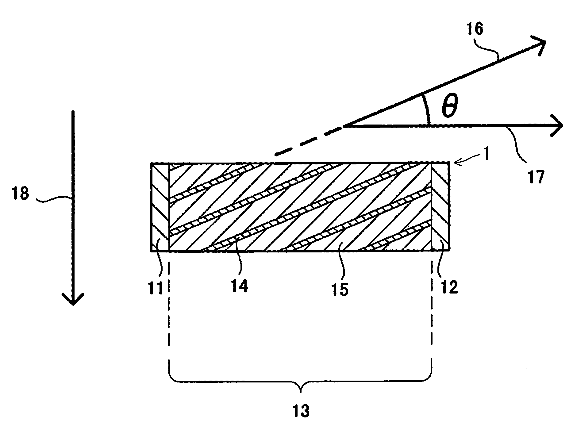
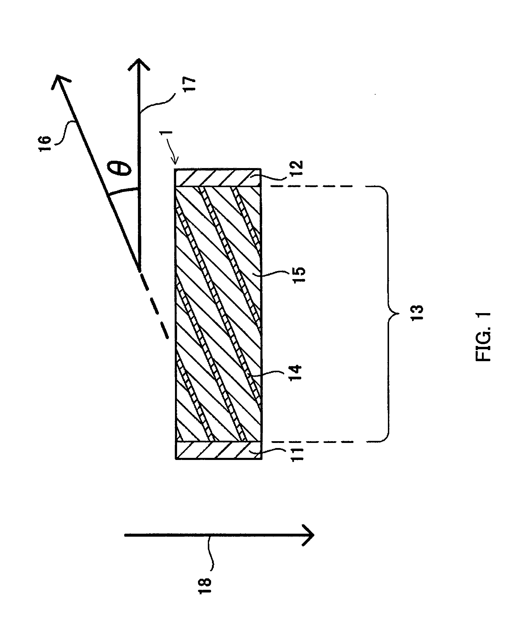
[0066]In Example 1, Bi and several kinds of metals (Au, Ag, Cu, or Al) were used to prepare a thermoelectric element 1 as shown in FIG. 1, and thermoelectric properties of the element were evaluated.

[0067]First, a Bi thin film having a thickness of 2.5 μm was formed by a sputtering method on the both surfaces of a metal foil (Au foil, Ag foil, Cu foil, or Al foil) having a size of 100 mm×100 mm and a thickness of 95 μm. A resulting sheet of Bi film / metal foil / Bi film was cut into small strips each having a size of 5 mm×50 mm, and 200 sheets of these strips were laminated and were subjected to compression bonding with applied heat at 250° C. for 1 hour, under a reduced pressure of 10−4 Pa and a load of 100 kg / cm2 applied in the direction the strips were laminated. This was followed by cutting and grinding to obtain a layered original plate having a size of 3 mm×48 mm and a thickness of 20 mm. Observation of a cross section of the original plate with a scanning electron microscope (SE...

example 2

[0075]According to the procedure of Example 1, elements with different thickness ratios of metal layer and Bi layer were prepared using Ag or Cu for the metal layer. Elements were prepared with the slant angle θ fixed at 30°, and by varying the thickness of the metal foil used for preparation at 70 μm, 80 μm, 90 μm, 95 μm, 98 μm, and 99 μm so that the periodically occurring metal-Bi layer had a thickness of 100 μm. Accordingly, the proportions in thickness of the Bi layer in the laminate of the resulting element were 30%, 20%, 10%, 5%, 2%, and 1%, respectively.

[0076]Table 2 below represents results of evaluation of power factor of the elements. The evaluation was carried out in the same manner as in Example 1.

TABLE 2Changes in power factor (μW / (cm · K2)) of the elementaccording to thickness proportion of Bi layer in the laminateProportion in thickness of Bi layer in laminate (%)302010521Ag8011015817511650Cu8010515516811040

[0077]As shown in Table 2, large power factors were obtained ...

example 3

[0078]According to the procedure of Example 1, elements were prepared by varying the slant angle θ and the thickness ratio of metal layer and Bi layer, using Cu for the metal layer. The slant angle θ was varied in 5° increment from 20° to 50°. The thickness of the Cu foil used for preparation was fixed at 20 μm, and the thickness of the Bi thin film formed on the surfaces of the Cu foil was varied at 0.25 μm, 0.5 m, 1 μm, 2 μm, 4 μm, and 8 μm.

[0079]Table 3 below represents results of evaluation of power factor of the elements. The evaluation was carried out in the same manner as in Example 1.

TABLE 3Changes in power factor (μW / (cm · K2)) of the element according to slant angle θ andthickness proportion of Bi layer in the laminate--Cu was used for the metal layerSlant angle θ(°)20253035404550Thickness of Bi layer8(μm) / 29(%)78828480726048in forming laminate4(μm) / 17(%)1001151181121089278(μm) / proportion in2(μm) / 9(%)118140152148146130110thickness of Bi layer in1(μm) / 5(%)105140160162158148...


PUM

PropertyMeasurementUnit
slant angleaaaaaaaaaa
power factoraaaaaaaaaa

Abstract

The invention provides a power generation method using a thermoelectric element, a thermoelectric element, and a thermoelectric device that excel in thermoelectric performance and are applicable to a wider range of applications over conventional counterparts. The element includes a first electrode and a second electrode that are disposed to oppose each other, and a laminate interposed between the first and second electrodes and electrically connected to both of the electrodes. The laminate has a structure in which a Bi layer and a metal layer made of a metal other than Bi are alternately layered, and the Bi layer and the metal layer having layer surfaces that are slanted with respect to a direction in which the first and second electrodes oppose each other. The element generates a potential difference between the electrodes by a temperature difference created along a direction perpendicular to the opposing direction of the first and second electrodes in the element. The power generation method and the thermoelectric device use this element.

Description

BACKGROUND OF THE INVENTION[0001]1. Field of the Invention[0002]The present invention relates to a power generation method using a thermoelectric element whereby electric energy is directly obtained from thermal energy. The present invention also relates to a thermoelectric element that directly converts thermal energy into electric energy, a fabrication method of the thermoelectric element, and a thermoelectric device.[0003]2. Related Background Art[0004]Thermoelectric generation is a technology for directly converting thermal energy into electric energy using the Seebeck effect, i.e. a phenomenon in which an electromotive force is generated in proportion to a temperature difference created between opposite ends of a substance. This technology has been used practically, for example, for a remote area power supply, a space power supply, and a military power supply.[0005]Conventional thermoelectric elements typically have a configuration known as the “π-type structure,” in which a p-...

Claims


Application Information

Patent Timeline
Patent Type & Authority Applications(United States)
IPC IPC(8): H01L35/28H01M6/00
CPCH01L35/18Y10T29/49112H01L35/34H01L35/32H10N10/853H10N10/01H10N10/17
Inventor KANNO, TSUTOMUADACHI, HIDEAKIYOTSUHASHI, SATOSHI
Owner PANASONIC CORP
Why Eureka
Try Eureka