Fiber optic seismic sensor based on MEMS cantilever

a technology of seismic sensors and fiber optics, applied in the direction of speed/acceleration/shock measurement, acceleration measurement using interia forces, instruments, etc., can solve the problem of accelerometers having an upper limit on the operating temperature of 75° c, spring deflection,

Active Publication Date: 2008-07-24
HALLIBURTON ENERGY SERVICES INC
View PDF99 Cites 27 Cited by
  • Summary
  • Abstract
  • Description
  • Claims
  • Application Information

AI Technical Summary

Problems solved by technology

However, the frequency range of these sensors is limited.
Unfortunately, the integrated circuits limit the maximum operating temperature of electronic MEMS to 75° C. The maximum temperature limit can be extended to 400° C. or more if optical fiber sensors are integrated with mechanical MEMS components so that no electronics are needed in the high temperature environment.
Ho

Method used


Image

  • Fiber optic seismic sensor based on MEMS cantilever
  • Fiber optic seismic sensor based on MEMS cantilever
  • Fiber optic seismic sensor based on MEMS cantilever

Examples


case 1

[0056]Consider Case 1

R3=0.037R4=0.33

P−V=0.168  (8)

case 2

[0057]Consider Case 2

R3=0.4R4=0.33

P−V=0.346  (9)

[0058]The modulation contrast P−V in Case 2 is more than twice that in Case 1. It is important to note that the “zeroes” in the interference pattern for Case 1 in FIG. 3 may not actually be zero due to electronic noise from the detectors and amplifiers. Assume equivalent electronic noise for Cases 1 and 2. Then Case 2 is preferred as a result of improved modulation contrast and heterodyne gain from the signal reflected from the reflective surface R3.

[0059]The analysis below demonstrates how spurious reflections can be limited to ≦45 dB (3.2×10⁻⁵) below the desired reflected power from the reflected surfaces R3 and R4, respectively. The fundamental problem in maintaining relatively small reflections is locating a bonding agent that can be used between the optical (input) fiber 30 and the glass wafer 17 that may be a borosilicate substrate. For example, locating a bonding agent that has an index of refraction midway between the refractiv...

first embodiment

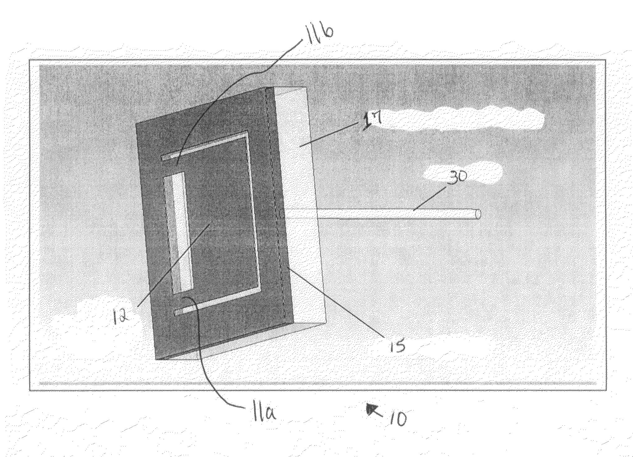
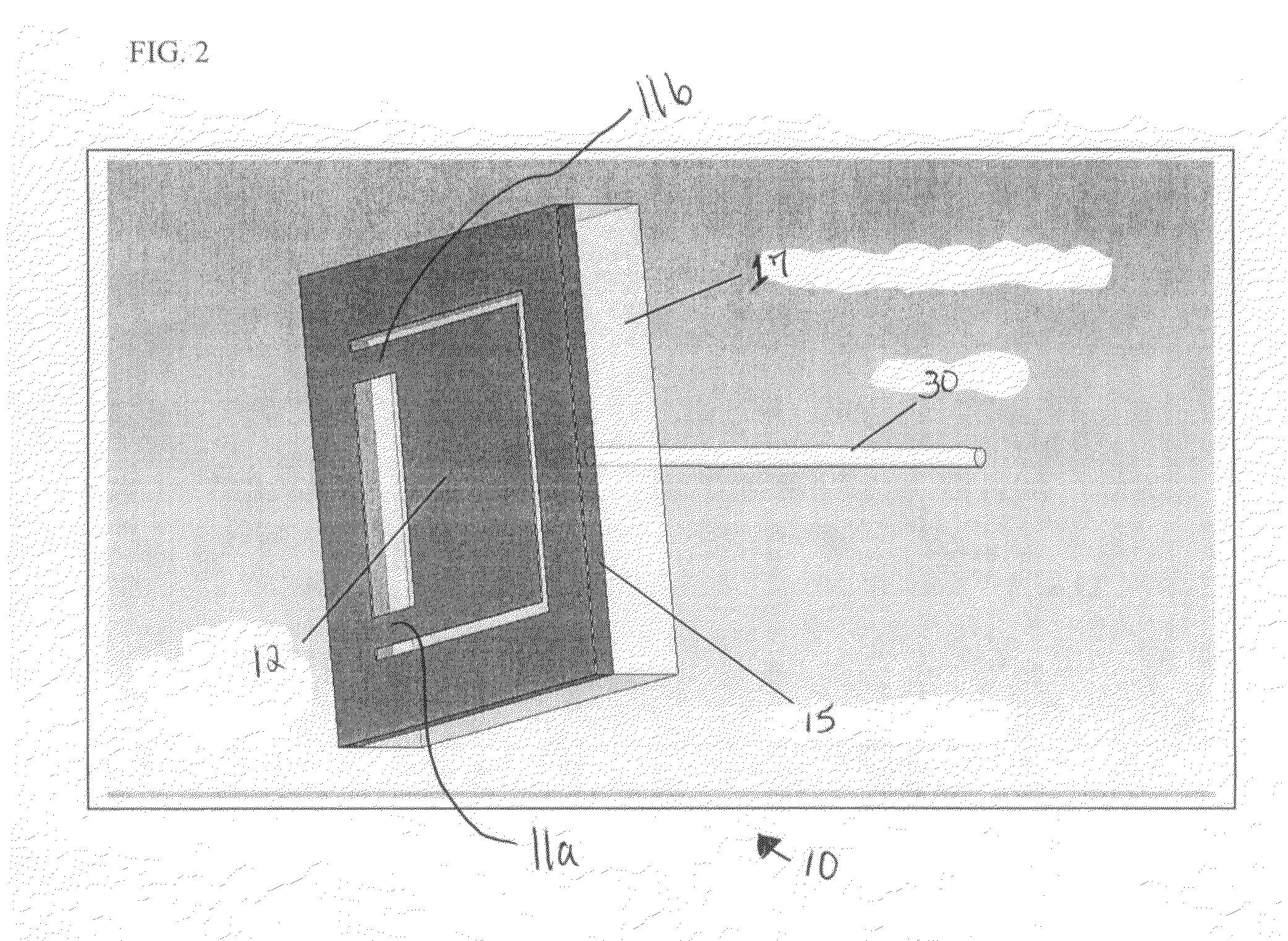
[0090]MEMS packaging for this application is important for success. Several embodiments for packaging are contemplated. However, one of ordinary skill in the art will appreciate that other packaging can be used for the present invention. In a first embodiment, the packaging is a single unit package. Referring to FIG. 2, the CTE (coefficient of thermal expansion) of silicon and borosilicate are substantially similar so that the two materials can be bonded and hermetically sealed. If the sensor 10 is packaged in a metal housing and the lid 40 is borosilicate, the borosilicate lid 40 may be bonded to a metal base plate. In an embodiment, the packaging is a triaxial package. The important issues with a triaxial package are the perpendicularity of the three orthogonal axes and the fiber bend radius. The objective is to hold the assembly in a cylindrical containment tube with as small a diameter as possible. The sensor containment tube must be pressure sealed against the high-pressure env...


PUM


Abstract

A dual cantilevered beam structure is attached to a silicon frame. An optical fiber extends from a borosilicate wafer bonded to the bottom of the frame. A second borosilicate wafer is bonded to the top of the frame. The bottom borosilicate wafer is bonded to the optical fiber with a bonding agent having an index of refraction between the refractive index of the fused silica optical fiber and the refractive index of the borosilicate wafer. In an embodiment, the bonding agent has a refractive index substantially similar to optical cement. Light is reflected into the optical fiber from the beam structure for measuring seismic changes.

Description

CROSS-REFERENCE TO RELATED APPLICATION[0001]This non-provisional patent application claims the benefit of U.S. Provisional Patent Application No. 60 / 792,878, entitled “FIBER OPTIC SEISMIC SENSOR BASED ON MEMS CANTILEVER,” filed Apr. 18, 2006, which is hereby incorporated in its entirety.FIELD OF THE INVENTION[0002]The present invention relates in general to fiber optic seismic sensors, and more particularly, to an interferometric micro-electro-mechanical system optical sensor to be used for seismic sensing.BACKGROUND[0003]The traditional method for detecting land seismic signals has been the coil-type geophone. Geophone sensors consist of a mass-spring assembly contained in a cartridge about 3 cm long and weighing about 75 grams. In a typical geophone sensor, the spring is soft and as the cartridge case moves, the mass (coil) is held in place by its own inertia. Thus, the coil serves as a reference for measurement of the cartridge displacement. The geophone sensor arrangement is ide...

Claims


Application Information

Patent Timeline
IPC IPC(8): G01B9/02G01P15/08
CPCG01P1/023G01V1/184G01P15/093G01P15/08
Inventor BERTHOLD, JOHN W.NEEDHAM, DAVID B.
Owner HALLIBURTON ENERGY SERVICES INC
Why Eureka
Try Eureka