
Optical filter and organic el display using the same

a technology of optical filter and organic el, applied in the field of optical filter, can solve the problems of slow incident efficiency of light into the color filter layer, attract attention, and low white light utilization ratio, and achieve the effects of preventing reflection in the inside, and reducing the size of the screen

Inactive Publication Date: 2008-07-31
DAI NIPPON PRINTING CO LTD
View PDF2 Cites 18 Cited by
  • Summary
  • Abstract
  • Description
  • Claims
  • Application Information

AI Technical Summary

Benefits of technology

Enhances light incident efficiency while reducing reflection and process complexity, allowing for higher performance and larger screen sizes in organic EL displays.

Problems solved by technology

Moreover, the disadvantage of the low white light utilization ratio when decomposing the color with color filters of the three primary colors, as in the organic EL display of the method (2), is solved so that the luminance of the display can be improved by heightening the conversion efficiency of the CCM layer, and thus it attracts the attention.
These reflection slower the incident efficiency of the light into the color filter layer, or the incident efficiency of the light into the cover conversion layer.
However, if a layer containing fine particles is laminated by coating or the like, for the purpose of (a) roughing, since a part of the light is lost due to the irregular reflection of the incident light, the incident efficiency from the display into the color filter layer or the color conversion layer is lowered.
Moreover, management of the paint for obtaining a certain roughened surface is difficult.

Method used


Image

  • Optical filter and organic el display using the same
  • Optical filter and organic el display using the same
  • Optical filter and organic el display using the same

Examples


example 1

Formation of the Black Matrix

[0114]As a transparent base material, a soda glass of 150 mm×150 mm, and 0.7 mm thickness (produced by Central Glass Co. Ltd.) was prepared. A thin film (thickness; 0.2 μm) of a nitride oxide composite chromium was formed on the entire surface of one side of the transparent base material by sputtering. By coating a photosensitive resist on the composite chromium thin film, a mask exposure, developing, etching of the composite chromium thin film and peeling off the resist are carried out in this order, a black matrix having 80 μm×280 μm rectangular shaped opening parts arranged on the matrix by a 100 μm pitch in the shorter side direction and a 300 μm pitch in the longer side direction was formed.

(Formation of the Color Filter Layer)

[0115]Photosensitive paint compositions for forming three color filter layers of red, green and blue were prepared. As the red coloring agent, a condensed azo based pigment (produced by Ciba-Geigy Japan Limited, Chromophtal re...


PUM

PropertyMeasurementUnit
wavelengthaaaaaaaaaa
Raaaaaaaaaaa

Abstract

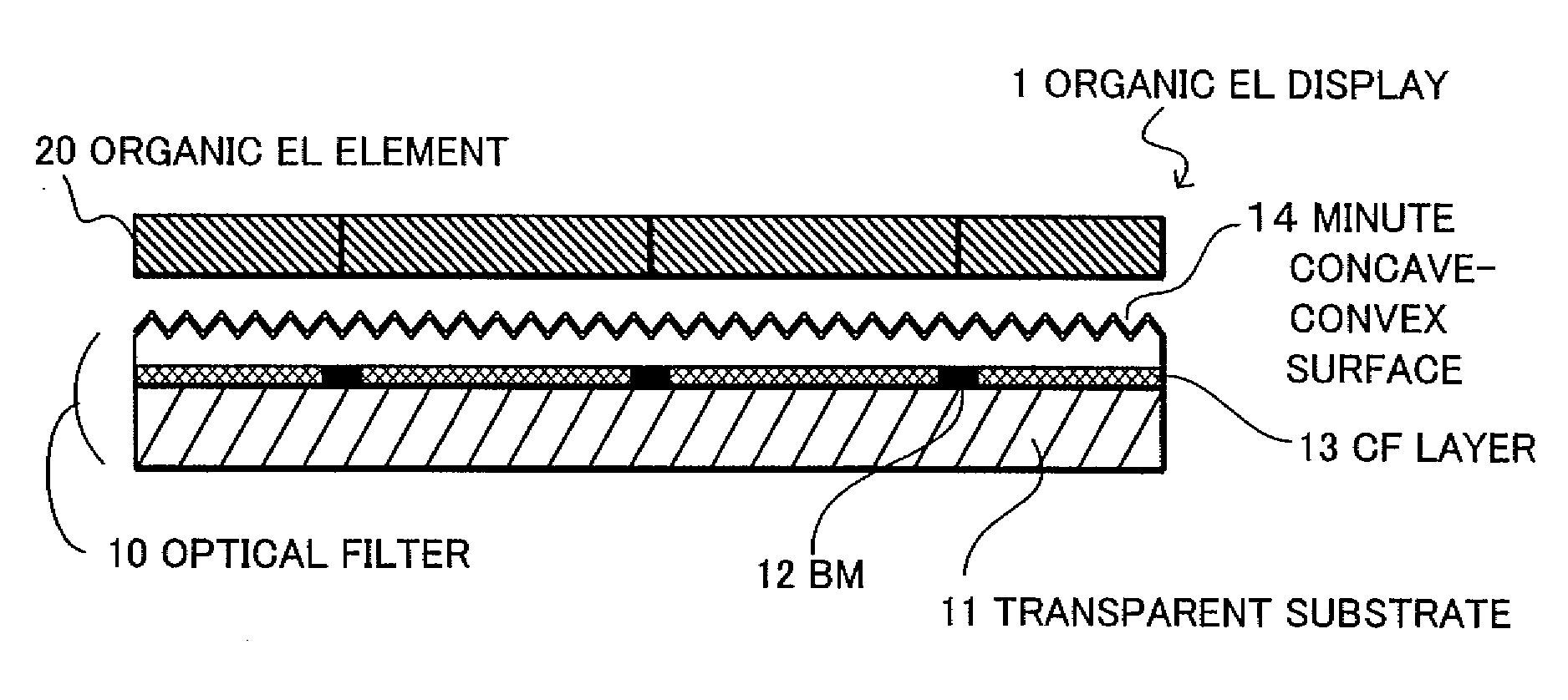
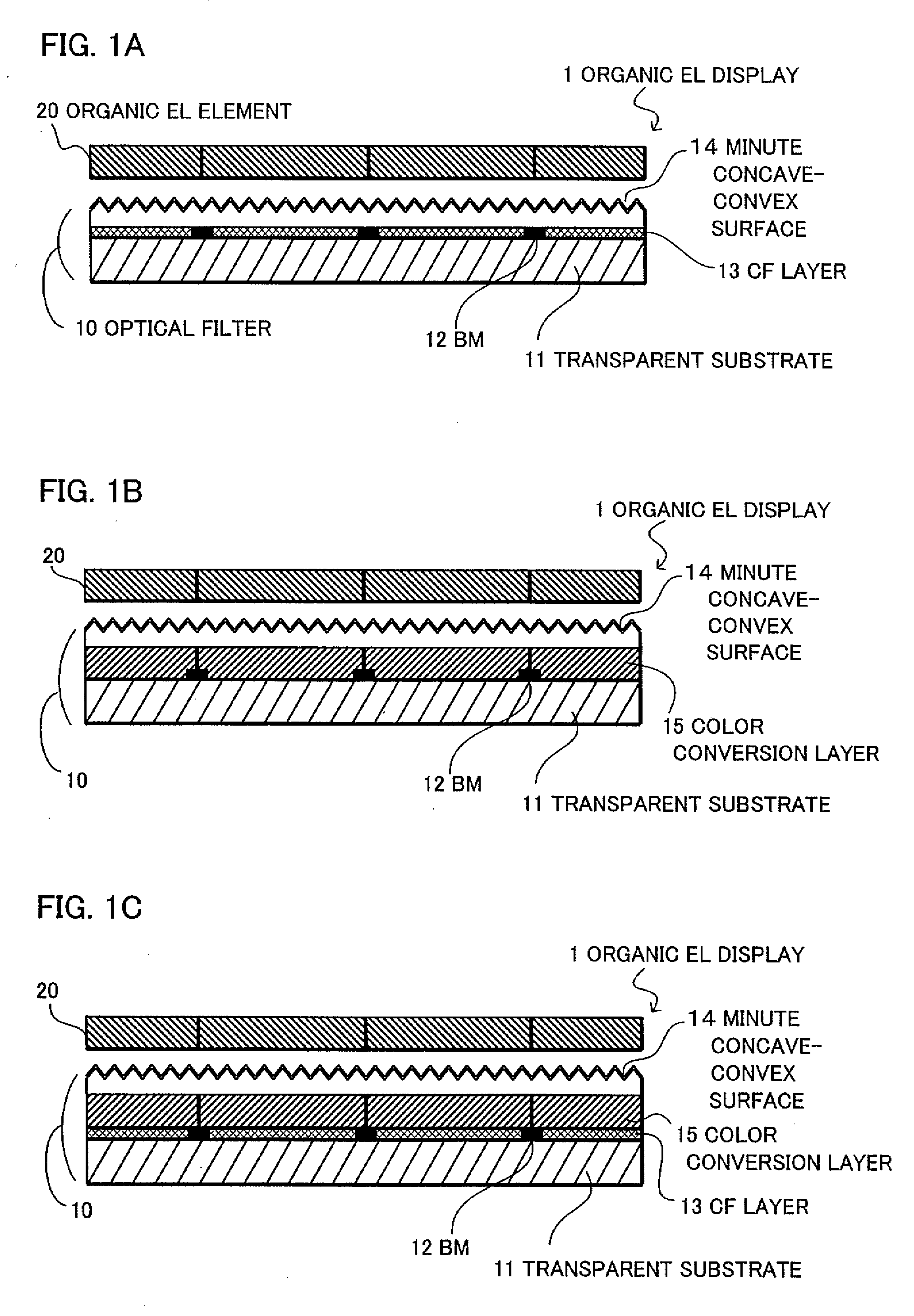
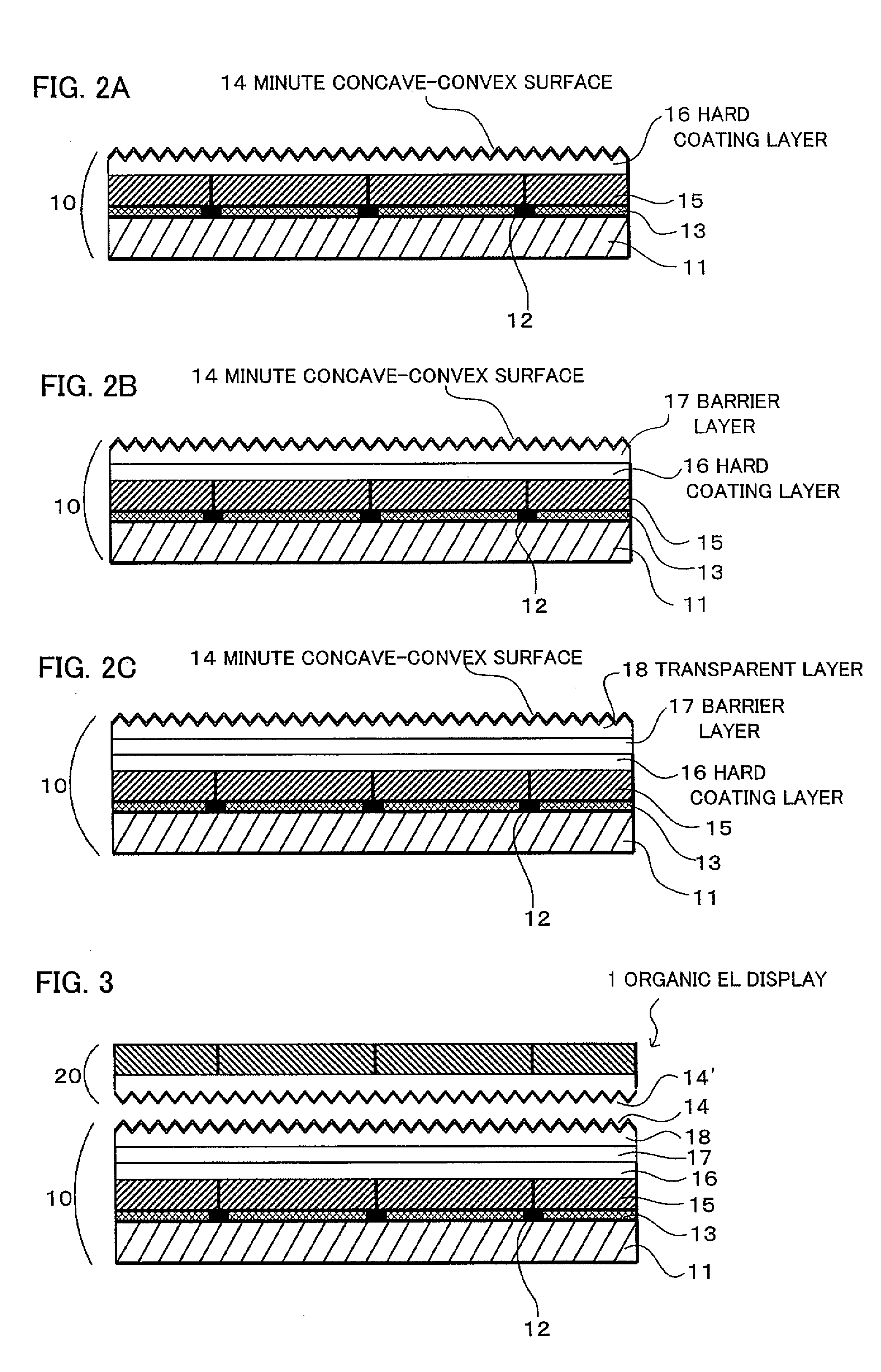
An object of the present invention is to solve the problem of losing a part of the incident light due to the irregular reflection of the incident light if a layer containing fine particles is formed by coating for the purpose of roughing when providing measures to prevent the reflection of the light at the surface of the color filter layer or at the surface of the color conversion layer inside a display, or a problem of difficulty in management of the paint for obtaining a certain roughened surface or a problem of increase of the number of processes to prevent the reflection when preventing the reflection by laminating plural layers of different refractive indices. By for example, laminating a black matrix 12, a color filter layer 13, a color conversion layer 15 or the like on a transparent substrate 11, and above thereof, combining an optical filter 10 having a minute concave-convex surface 14, with an endless number of minute concave-convex by a pitch of the wavelength of the light or less formed, with an organic EL element 20, the object can be achieved.

Description

BACKGROUND OF THE INVENTION[0001]1. Field of the Invention[0002]The present invention relates to an improved optical filter capable of efficiently preventing reflection of the light between an optical filter such as a color filter substrate and a color converting substrate, and a light emitting part in various kinds of displays such as an organic electroluminescent (EL) display, in particular, capable of improving the light incident efficiency to the optical filter, and a display comprising the same, in particular, an organic EL display.[0003]2. Description of the Related Art[0004]The organic EL element, in principle, has a structure with an organic EL light emitting layer interposed in between an anode and a cathode. For providing an organic EL display capable of providing the color display using an organic EL element practically, there are (1) a method of arranging organic EL elements each emitting the three primary colors, (2) a method of combining an organic EL element for emitt...

Claims


Application Information

Patent Timeline
Patent Type & Authority Applications(United States)
IPC IPC(8): H01J1/62G02B1/11G02B5/20H01L27/32H01L51/50H01L51/52H05B33/12
CPCG02B5/201H01L27/322H01L51/5262H01L51/5284Y10S428/917Y10T428/25Y10T428/24537Y10T428/24355Y10T428/2457H10K59/38H10K59/875H10K59/8792H10K50/85H10K50/865
Inventor BABA, YASUKOASANO, MASAAKI
Owner DAI NIPPON PRINTING CO LTD
Learn More