Encoded mechanism for source synchronous strobe lockout

a synchronous strobe and lockout technology, applied in the field of microelectronics, can solve problems such as core operating voltage, data strobe errors due to data strobe glitches on a source synchronous bus, and data strobe errors subject to errors

Active Publication Date: 2008-07-31
VIA TECH INC
View PDF20 Cites 23 Cited by
  • Summary
  • Abstract
  • Description
  • Claims
  • Application Information

AI Technical Summary

Benefits of technology

[0015]The present invention provides a superior technique for locking out a source synchronous strobe receiver that is continually updated to compensate for variations in bus clock frequency, voltage, and temperature. In one embodiment, an apparatus for precluding reception errors in an source synchronous receiver is provided. The apparatus includes a delay-locked loop and one or more strobe receivers. The delay-locked loop receives a reference clock signal and generates a select vector signal and an encoded select vector signal, where the encoded select vector signal indicates a lockout time period, and where the select vector signal is employed to select, one of a plurality of successively delayed versions of the reference clock signal that lags the reference clock signal by a prescribed number of cycles of the reference clock signal, and where the lockout time period is slightly less than the prescribed number of cycles of the reference clock signal. The delay-locked loop has a gray encoder that generates the encoded select vector signal according to a gray code. The one or more strobe receivers are each coupled to the delay-locked loop. Each of the one or more strobe receivers receives the encoded select vector signal and a corresponding strobe signal, where the each is configured to lock out reception of the corresponding strobe signal for the lockout time period following transition of the corresponding strobe signal, and where the encoded select vector signal is employed to determine the lockout time period by selecting one of a plurality of successively delayed versions of the corresponding strobe signal, and where the each comprises a gray code mux to select the one of a plurality of successively delayed versions of the corresponding strobe signal according to the encoded select vector signal.

Problems solved by technology

But data strobes are subject to error resulting from a number of sources including, but not limited to, conducted and radiated emissions from other signals in close proximity.
And whereas former bus protocols provided sampling mechanisms to detect and correct errors on the bus, errors due to data strobe glitches on a source synchronous bus are considered more complex because there is no absolute time reference, such as was provided for in former bus protocols by a number of bus clock cycles, that can be relied upon to determine if a transition on a strobe signal is a real transition or a glitch.
But these techniques employ fixed logic, typically a string of inventers, to calculate the lockout time and, consequently, when operating parameters change, such as slight variations in bus clock frequency, variations in device temperature, and variations in core operating voltage, lockout time is adversely affected.
In addition, fabrication process variations can cause lockout time to vary from part to part.
Thus, designers are forced to employ worst-case scenarios to employ these techniques.
The present inventors have noted that conventional receiver lockout techniques are deficient because they do not provide any compensation for the above noted variations, and thus a substandard mechanism is provided through which error is introduced into a computer system design.

Method used


Image

  • Encoded mechanism for source synchronous strobe lockout
  • Encoded mechanism for source synchronous strobe lockout
  • Encoded mechanism for source synchronous strobe lockout

Examples


Embodiment Construction

[0027]The following description is presented to enable one of ordinary skill in the art to make and use the present invention as provided within the context of a particular application and its requirements. Various modifications to the preferred embodiment will, however, be apparent to one skilled in the art, and the general principles defined herein may be applied to other embodiments. Therefore, the present invention is not intended to be limited to the particular embodiments shown and described herein, but is to be accorded the widest scope consistent with the principles and novel features herein disclosed.

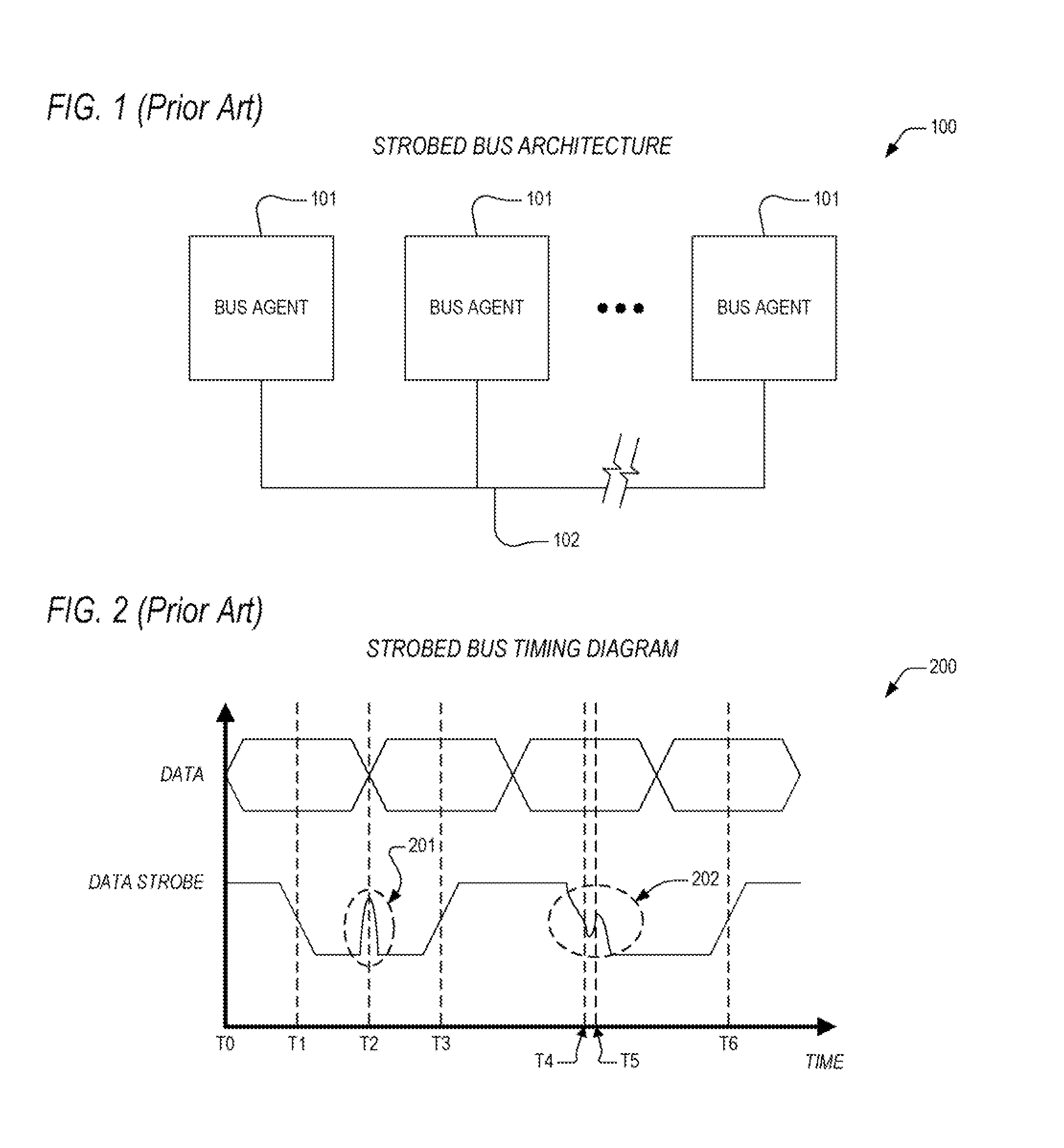
[0028]In view of the above background discussion on present day techniques that are employed within present day integrated circuits for the detection and correction of errors that occur in a source synchronous system bus, a discussion of the limitations and disadvantages of these techniques will now be presented with reference to FIGS. 1-2. Following this, a discussion of the p...


PUM


Abstract

An apparatus for locking out a source synchronous strobe receiver, including a delay-locked loop (DLL) and receivers. The DLL receives a reference clock, and generates a select vector and an encoded select vector. The select vector is employed to select a delayed version of the reference clock that lags the reference clock by a prescribed number of cycles. The select vector is reduced by an amount and is gray encoded to indicate the lockout time. The receivers are each coupled to the delay-locked loop. Each of the receivers receives the encoded select vector and a corresponding strobe, and locks out reception of the corresponding strobe for the lockout time following transition of the corresponding strobe. The encoded select vector is employed by a gray code mux therein to determine the lockout time by selecting a delayed version of the corresponding strobe.

Description

CROSS-REFERENCE TO RELATED APPLICATIONS[0001]This application claims the benefit of the following U.S. Provisional Applications, each of which is herein incorporated by reference for all intents and purposes.SERIALFILINGNUMBERDATETITLE60887007Jan. 29,ENCODED MECHANISM FOR SOURCE(CNTR.2296)2007SYNCHRONOUS STROBE LOCKOUT[0002]This application is related to the following co-pending U.S. Patent Applications, each of which has a common assignee and common inventors.SERIALFILINGNUMBERDATETITLE                                 APPARATUS AND METHOD FOR(CNTR.2280)LOCKING OUT A SOURCESYNCHRONOUS STROBE RECEIVER                                 ADJUSTMENT MECHANISM FOR SOURCE(CNTR.2295)SYNCHRONOUS STROBE LOCKOUT                                 DOUBLE-PUMPED / QUAD-PUMPED(CNTR.2297)VARIATION MECHANISM FOR SOURCESYNCHRONOUS STROBE LOCKOUT                                 RECEIVER MECHANISM FOR SOURCE(CNTR.2406)SYNCHRONOUS STROBE LOCKOUTBACKGROUND OF THE INVENTION[0003]1. Field of the Invention[0004]T...

Claims


Application Information

Patent Timeline
Patent Type & Authority Applications(United States)
IPC IPC(8): H03L7/06
CPCH03L7/0805H04L7/0008H03L7/0814
Inventor GASKINS, DARIUS D.LUNDBERG, JAMES R.
Owner VIA TECH INC
Why Eureka
Try Eureka