
Projector

a projector and projector technology, applied in the field of projectors, can solve the problems of reducing portability, unable to receive information with sufficient accuracy, and using presentation information or picture information for other purposes without the permission of the person having copyright of information, so as to achieve the effect of convenient and portabl

Active Publication Date: 2008-07-31
SEIKO EPSON CORP
View PDF23 Cites 66 Cited by
  • Summary
  • Abstract
  • Description
  • Claims
  • Application Information

AI Technical Summary

Benefits of technology

[0010]It is an advantage of some aspects of the invention to provide an easy and portable projector capable of overlapping and displaying both a visible color image and invisible infrared image on one projection surface such that display image (image and picture) can be controlled particularly by one system

Problems solved by technology

When excessive volume of information is on display at a time, a person cannot receive information with sufficient accuracy just as a case where he or she has difficulty in obtaining necessary information in a busy shopping area of a city crowded with signboards.
Shooting and using presentation information or picture information for other purposes without permission of the person having copyright of the information has been currently a serious social problem.
Considering that the number of portable projector is increasing as a result of size reduction of projector, addition of the second projector lowers portability.
However, particularly for the infrared projector which projects invisible infrared images, the display position cannot be visually controlled.
Accordingly, freedom of installation and easiness of use extremely lower.
Furthermore, the overall compactness of the display system increases portability of the system.
Thus, there is a high possibility that optical aberration such as color aberration is produced.
In this case, deterioration of the light modulation element and the polarizing element is easily caused.

Method used


Image

  • Projector
  • Projector
  • Projector

Examples


first embodiment

[0053]A first embodiment according to the invention hereinafter described with reference to FIGS. 1 and 2A through 2D.

[0054]In this embodiment, an example of a liquid crystal projector which includes one light source and one transmission type liquid crystal, light valve is discussed.

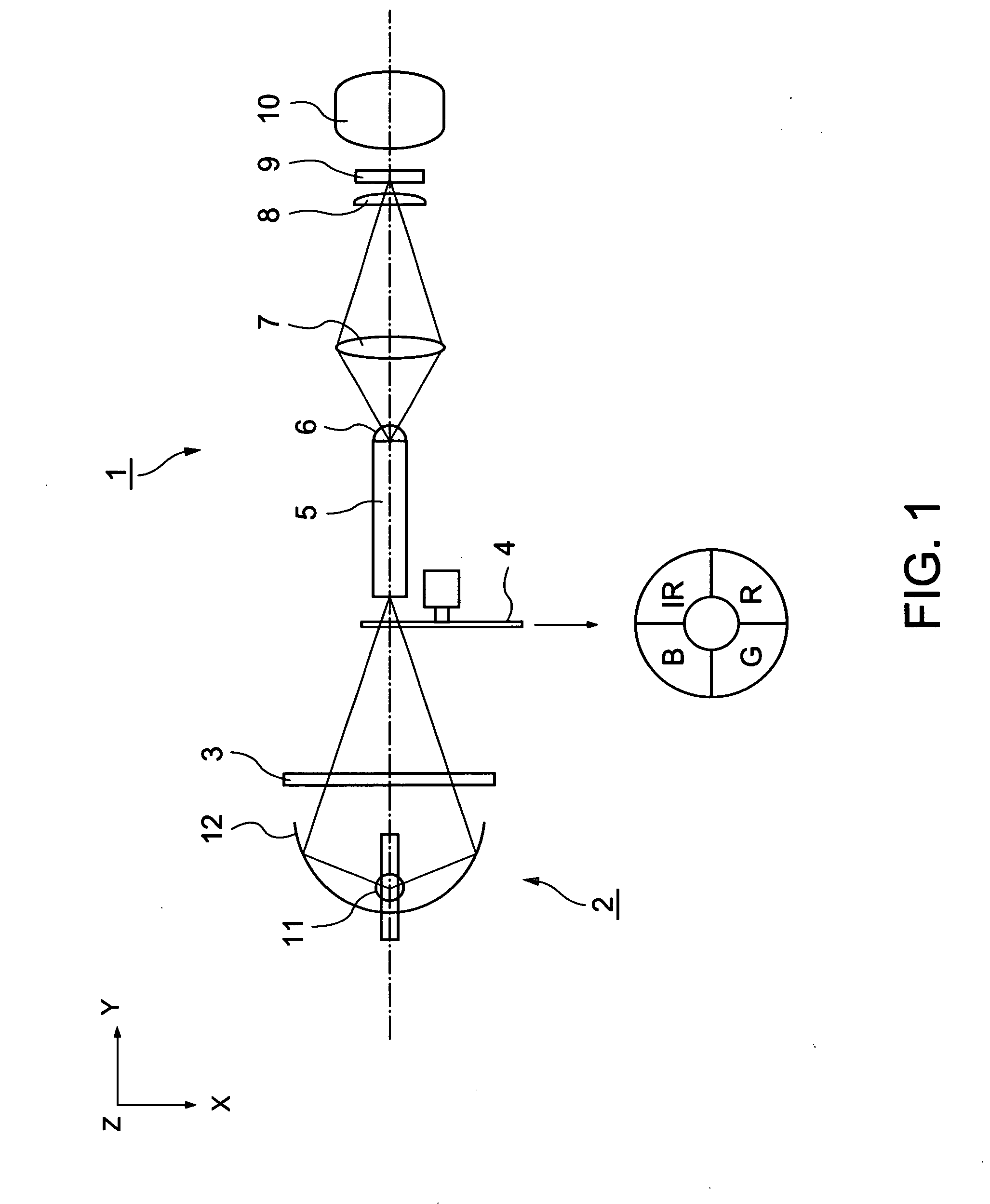
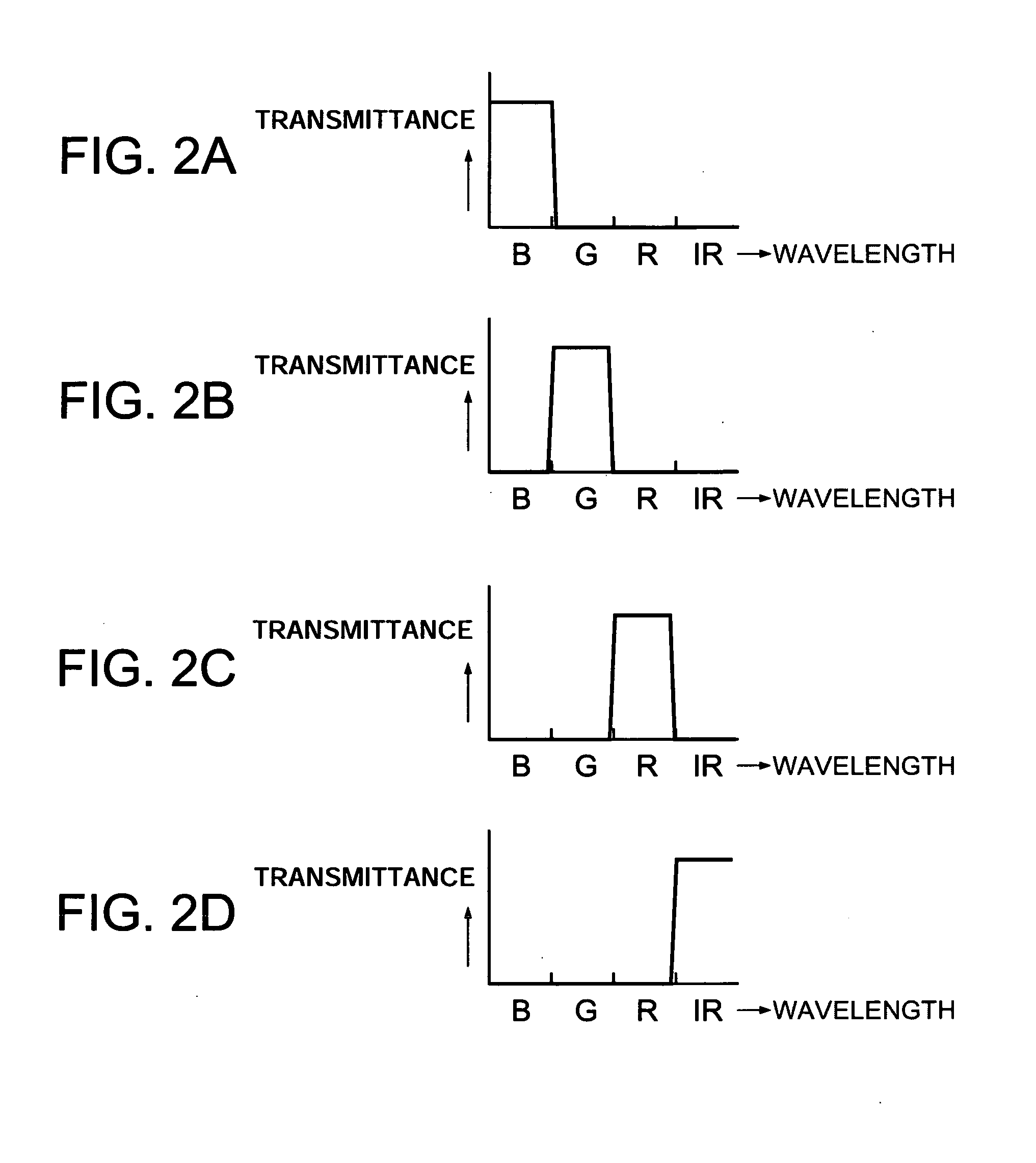
[0055]FIG. 1 schematically illustrates a structure of the project or according to this embodiment and FIGS. 2A through 2D show spectral characteristics of a rotational color filter used in the projector.

[0056]It should be noted that the size and positional relations contained in the respective figures are different for each figure for clearly showing the respective components.

[0057]As illustrated in FIG. 1, a projector 1 according to this embodiment generally includes a light source 2, an ultraviolet light cut filter 3, a rotational color filter 4 (light time division unit) a rod integrator 5, relay lenses 6, 7 and 8, a transmission type liquid crystal light valve 9 (light modulation element, hereinafter...

second embodiment

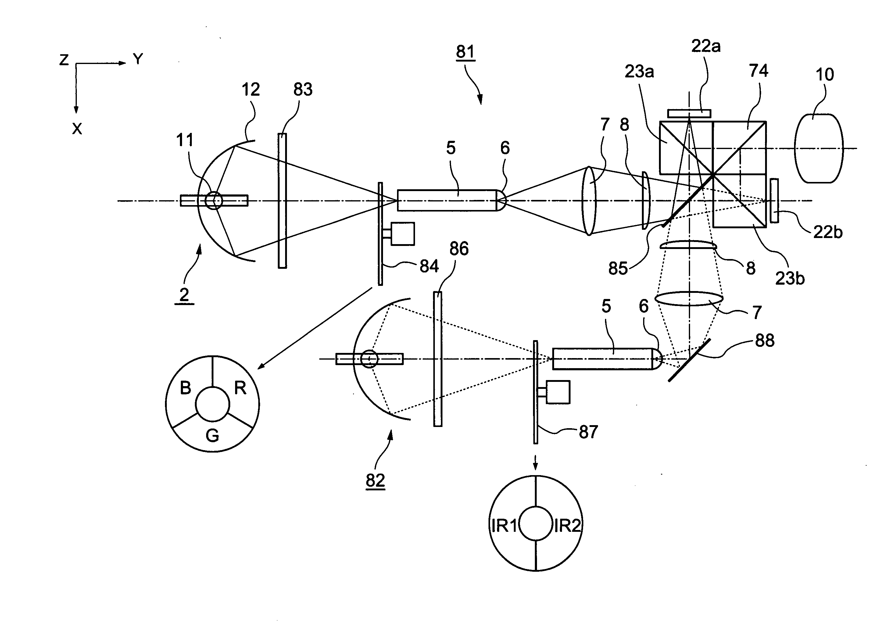
[0070]A second embodiment according to the invention is now described with reference to FIG. 3.

[0071]The basic structure of a projector according to this embodiment is substantially equivalent to that of the projector in the first embodiment shown in FIG. 1, but is different in that a reflection type liquid crystal light valve is used in lieu of the transmission type liquid crystal light valve used in the first embodiment.

[0072]FIG. 3 schematically illustrates the structure of the projector according to this embodiment. In FIG. 3, similar reference numbers are given to components common to those used in the first embodiment in FIG. 1, and detailed explanation of those components is not repeated.

[0073]According to a projector 21 in this embodiment illustrated in FIG. 3, a polarized beam splitter PBS) prism 23 is provided between the relay lens 8 and reflection type liquid crystal light valve 22 light modulation element, hereinafter abbreviated as liquid crystal light valve in some ca...

third embodiment

[0077]A third embodiment according to the invention is now described with reference to FIG. 4.

[0078]The basic structure of a projector according to this embodiment is substantially equivalent to that of the projector in the first embodiment, but is different in that a time division driving type reflection type small mirror array device is used in lieu of the liquid crystal light valve used in the first or second embodiment.

[0079]FIG. 4 schematically illustrates the structure of the projector according to this embodiment. In FIG. 4, similar reference numbers are given to components common to those used in the first embodiment shown in FIG. 1, and detailed explanation of those components is not repeated.

[0080]According to a projector 31 in this embodiment illustrated in FIG. 4, a TIR prism 33 containing a total reflection surface 33a which achieves total reflection of light entering at a specific angle is provided between the relay lens 8 and a reflection type small mirror array light...


PUM


Abstract

A projector includes: a light source which emits light containing visible light and infrared light; a light time division unit which divides light emitted from the light source into one or more visible lights having different wavelength ranges and one or more infrared lights having different wavelength ranges in a time-division manner; a light modulation element which time-sequentially modulates the plural lights separated by the light time division unit and having different wavelength ranges; and a projection unit which projects and displays the light modulated by the light modulation element on a projection-receiving surface. A plurality of images containing a visible image produced by the one or more visible lights and an infrared image produced by the one or more infrared lights are displayed on the same projection receiving surface.

Description

BACKGROUND[0001]1. Technical Field[0002]The present invention relates to a projector and more particularly to a projector capable of displaying both visible image and infrared image on a screen.[0003]2. Related Art[0004]A projector which displays an enlarged optical image on a screen as image information created by using an optical modulation element has high adjustability to digital equipment such as a computer. Thus, this type of projector has been widely used for the purpose of presentation, information, showing pictures, and other purposes. Since the chief function of a general display apparatus including a projector is to provide some implicational information for a person, image information to be displayed is generally given as a visible image which is visible to human eyes. Accordingly, a typical projector selects visible light from light emitted from a light source, and displays an image by using the selected visible light as illumination light.[0005]For displaying implicati...

Claims


Application Information

Patent Timeline
Patent Type & Authority Applications(United States)
IPC IPC(8): G03B21/14
CPCG03B21/14G02B26/008G02B27/1006G02B27/141G03B21/005G03B33/08
Inventor ITO, YOSHITAKA
Owner SEIKO EPSON CORP
Features
  • Generate Ideas
  • Intellectual Property
  • Life Sciences
  • Materials
  • Tech Scout
  • Unparalleled Data Quality
  • Higher Quality Content
  • 60% Fewer Hallucinations
Learn More