Variable capacitor

a variable capacitor and capacitor technology, applied in the field of variable capacitors, can solve the problem of significant charge of dielectric films, and achieve the effects of preventing reducing the variation ratio of static capacitance, and suppressing the fluctuation of driving voltage characteristics

Active Publication Date: 2008-07-31
FUJITSU LTD
View PDF14 Cites 21 Cited by
  • Summary
  • Abstract
  • Description
  • Claims
  • Application Information

AI Technical Summary

Benefits of technology

[0062]In this variable capacitor, the conductor pattern which is smaller in area than the dielectric film located thereunder comes into direct contact with the movable capacitor electrode film (the first opposing face) or the fixed capacitor electrode (the second opposing face), under the state where the spacing between the electrodes becomes minimal over the entire region between the first opposing face of the movable capacitor electrode film and the second opposing face of the fixed capacitor electrode (the second state). In this variable capacitor, therefore, the fluctuation of the driving voltage characteristic can be prevented, for substantially the same reason as described regarding the variable capacitor according to the fifth aspect.
[0063]Thus, the variable capacitor according to the eleventh aspect of the present invention is appropriate for suppressing the fluctuation in driving voltage characteristic, and achieving a larger variation ratio of the static capacitance.
[0064]A twelfth aspect of the present invention provides a variable capacitor comprising a movable capacitor electrode film having a first opposing face, a fixed capacitor electrode having a second opposing face opposing the first opposing face and a curved portion protruding toward the movable capacitor electrode film or in an opposite direction of the movable capacitor electrode film, a dielectric film provided on one of the first opposing face and the second opposing face, and a conductor pattern buried in the di...

Problems solved by technology

Accordingly, repeated contacts between the movable electrode and the dielectric film on the surface of th...

Method used


Image

  • Variable capacitor
  • Variable capacitor
  • Variable capacitor

Examples


first embodiment

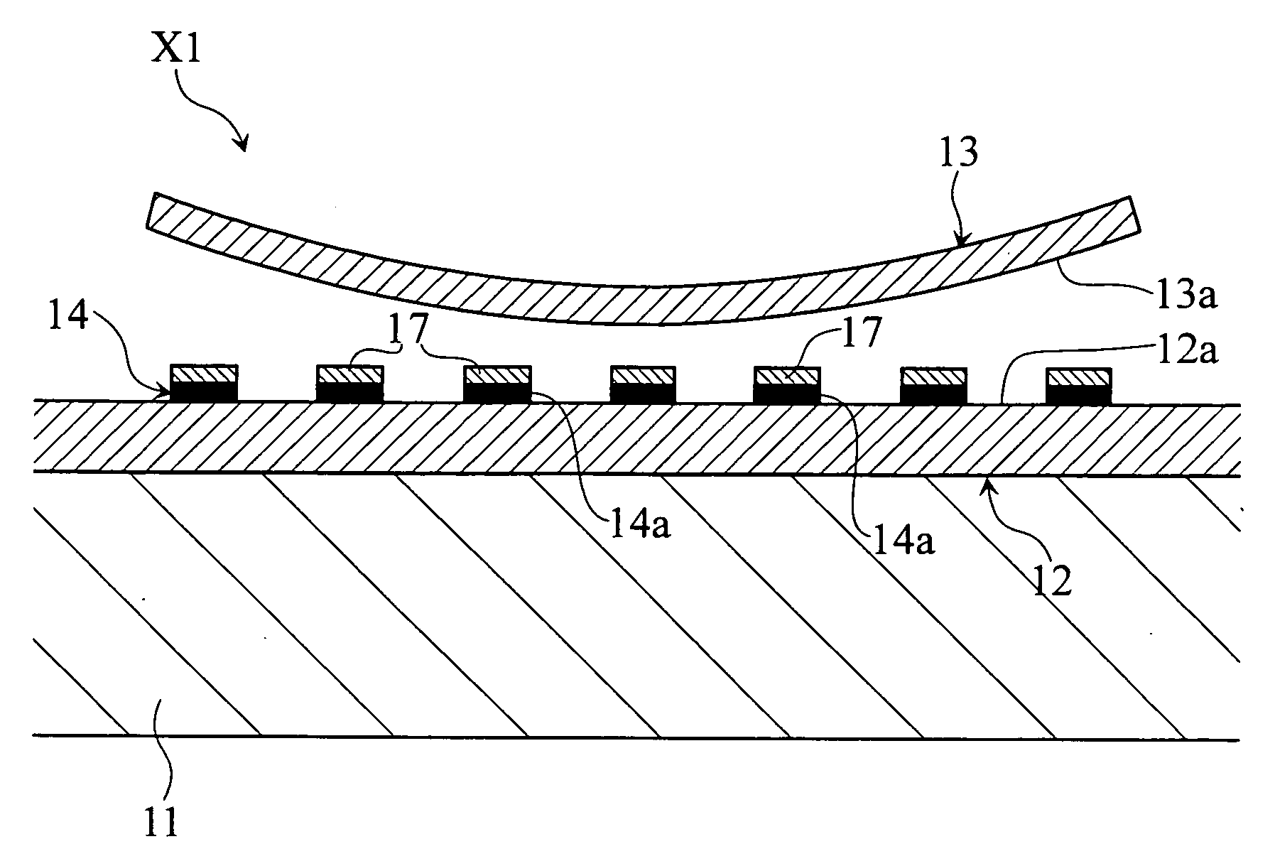
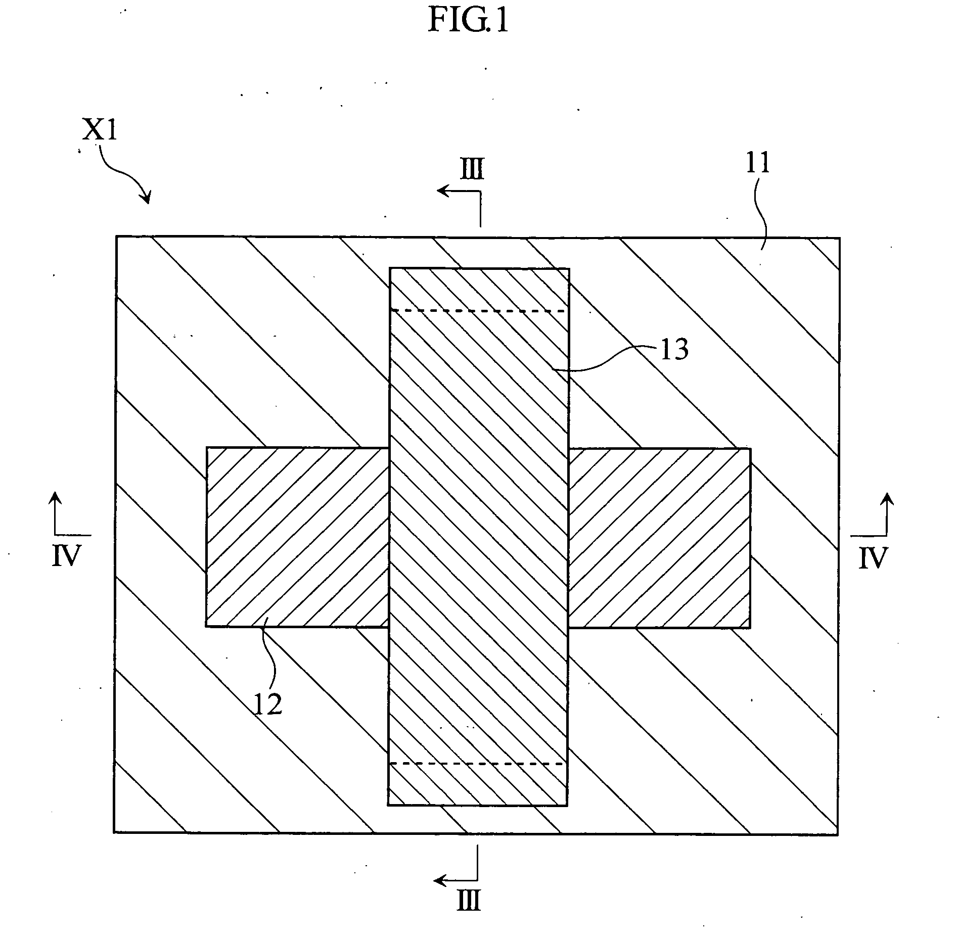
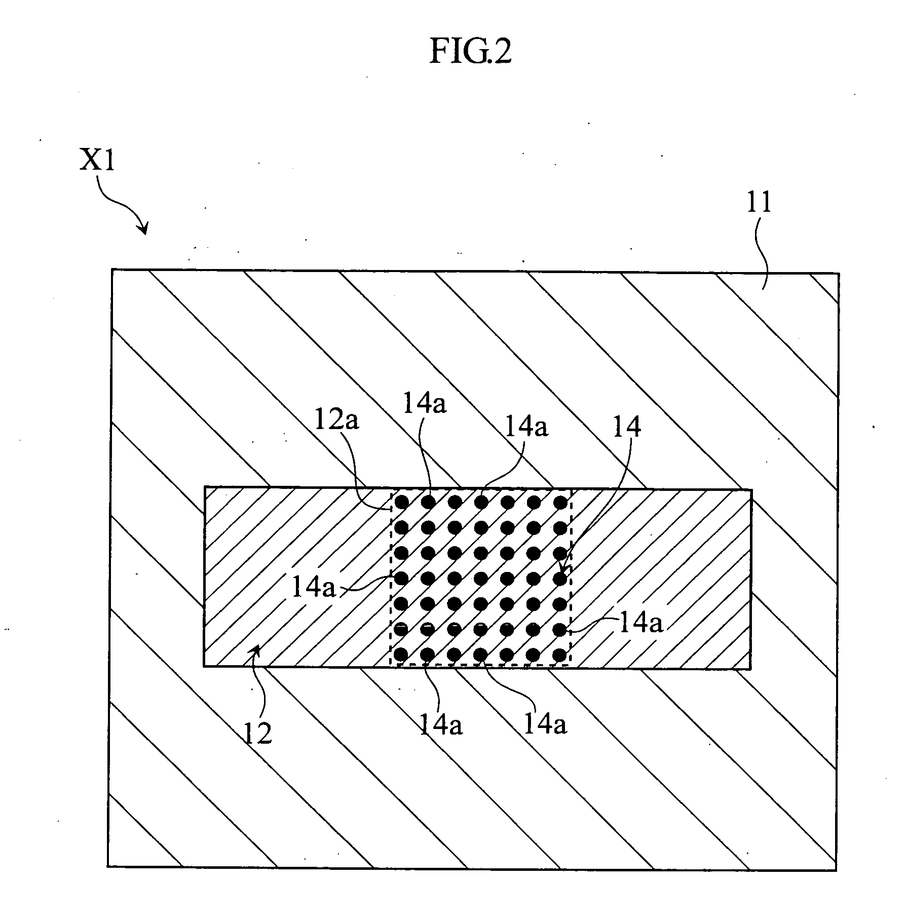
[0102]FIGS. 1 to 4 depict a variable capacitor X1 according to the present invention. FIG. 1 is a plan view showing the variable capacitor X1. FIG. 2 is a fragmentary plan view showing the variable capacitor X1. FIG. 3 is a cross-sectional view taken along the line III-III in FIG. 1. FIG. 4 is an enlarged fragmentary cross-sectional view taken along the line IV-IV in FIG. 1. The variable capacitor X1 includes a substrate 11, a fixed electrode 12, a movable electrode 13 (not shown in FIG. 2), and a dielectric pattern 14.

[0103]The substrate 11 is made of a silicon material, for example. On the substrate 11, a predetermined interconnect pattern (not shown) is provided for electrical connection with the fixed electrode 12 or the movable electrode 13.

[0104]The fixed electrode 12 is formed in a pattern on the substrate 11, and constitutes a part of a pair of capacitor electrodes provided in the variable capacitor X1. The movable electrode 13 is erected on the substrate 11 as shown in FIG....

second embodiment

[0124]FIG. 12(a)-(b) is a fragmentary cross-sectional view showing a variable capacitor X2 according to the present invention. The variable capacitor X2 includes the substrate 11, the fixed electrode 12, the movable electrode 13 of a curved shape, a dielectric film 21, and a conductor pattern 22. The variable capacitor X2 is different from the variable capacitor X1 in including the dielectric film21 and the conductor pattern 22, in place of the dielectric pattern 14.

[0125]The dielectric film 21 in the variable capacitor X2 serves to prevent a short-circuit between the fixed electrode 12 and the movable electrode 13. The dielectric film 21 is formed of a silicon oxide film, for example. The conductor pattern 22 is formed in a pattern on the opposing face 13a of the movable electrode 13, and includes a plurality of conductor islands 22a spaced from each other, for example as shown in FIG. 13. The surface of the conductor pattern 22 opposing the dielectric film 21 is smaller in area th...

third embodiment

[0128]FIG. 14(a)-(b) is a fragmentary cross-sectional view showing a variable capacitor X3 according to the present invention. The variable capacitor X3 includes the substrate 11, the fixed electrode 12, the movable electrode 13 of a curved shape, the dielectric film 21, and a conductor pattern 23. The variable capacitor X3 is different from the variable capacitor X1 in including the dielectric film 21 and the conductor pattern 23, in place of the dielectric pattern 14.

[0129]The dielectric film 21 in the variable capacitor X3 serves to prevent a short-circuit between the fixed electrode 12 and the movable electrode 13. The conductor pattern 23 is formed in a pattern on the dielectric film 21, and includes a plurality of conductor islands 23a spaced from each other, for example as shown in FIG. 15. The conductor pattern 23 occupies a smaller area on the dielectric film 21, than the dielectric film 21 located thereunder. The conductor pattern 23 may be formed of nickel or titanium.

[01...


PUM


Abstract

A variable capacitor is provided which is appropriate for suppressing fluctuation in driving voltage characteristic and for achieving a larger variation ratio of static capacitance. The variable capacitor includes a fixed electrode and a movable electrodetrode. The fixed electrode includes a first opposing face, while the movable electrode includes a second opposing face that faces the first opposing face. The movable electrode further includes a curved portion that protrudes toward the fixed electrode. The variable capacitor also includes a dielectric pattern provided on the first opposing face.

Description

BACKGROUND OF THE INVENTION[0001]1. Field of the Invention[0002]The present invention relates to a variable capacitor capable of changing static capacitance.[0003]2. Description of the Related Art[0004]In the technical field of wireless communication equipments such as a mobile phone, the increase in number of components to be incorporated in the equipment for achieving higher performance has been creating growing demand for smaller sizes of high-frequency and RF circuits. In order to satisfy such demand, a technique called micro-electromechanical systems (hereinafter, MEMS) has been employed for micronization of various components constituting the circuit, including a variable capacitor. The variable capacitor is an essential component in a variable-frequency transmitter, a tuned amplifier, an impedance matching circuit and so on. The variable capacitor that can be obtained based on the MEMS technique can be found, for example, in the patent documents 1 and 2 cited here below.[0005...

Claims


Application Information

Patent Timeline
IPC IPC(8): H01G5/04
CPCH01G5/01H01G5/18H01G5/16H01G5/04H01G5/013
Inventor SHIMANOUCHI, TAKEAKIIMAI, MASAHIKOYONEZAWA, YUMI, XIAOYUUEDA, SATOSHI
Owner FUJITSU LTD
Why Eureka
Try Eureka