Shared Radio Backhaul System

a radio backhaul and radio backhaul technology, applied in the field of wireless communications networks, can solve the problems of high cost of backhaul methods, increased operating expenses associated with adopting multiple leased lines, and increased costs of backhaul methods

Inactive Publication Date: 2008-07-31
APPLE INC
View PDF11 Cites 52 Cited by
  • Summary
  • Abstract
  • Description
  • Claims
  • Application Information

AI Technical Summary

Benefits of technology

[0023]As is known in the art, a frame format represents an allocation of radio resources, and includes slots that define use of the radio resources by various equipment for a variety of purposes; the frame format may allocate frequency slots and time slots. In a system that uses time division duplexing for transmission between user equipment and base stations, according to the first aspect of the present invention, timeslots allocated to transmissions between base stations in the second frame format will occur wholly within timeslots allocated to transmission from base stations to user equipment within the first format. Consequently transmissions between base stations will not occur when transmissions from user equipment are received at base stations. As a result, interference from transmissions between base stations to the reception of transmissions from user equipment at a base station that is operating according to the first frame format is avoided.
[0024]In a system that uses frequency division duplexing of the links between user equipment and base stations, frequencies allocated to transmissions between base stations according to the second frame format will be wholly within frequency allocations associated with signals that are transmitted from base stations to user equipment according to the first format. Consequently, transmissions between base stations do not occur within the frequency allocation used for transmissions from user equipment to base stations. As a result, interference from transmissions between base stations to the reception of transmissions from user equipment at a base station that is operating according to the first frame format is avoided.
[0027]Advantageously, the second antenna system comprises an antenna array having a plurality of antenna elements and the first antenna system comprises a sub-set of said antenna elements. The benefit of this is that the surface area of the antenna system is reduced compared to the use of separate antennas which reduces wind loading. In addition, component cost may be reduced.

Problems solved by technology

Consequently, the operational expense associated with adopting multiple leased lines has also increased, making this a potentially expensive option for high capacity systems.
However each of these methods of backhaul has associated costs.
Dedicated fibre links can be expensive in terms of capital expense due mainly to the cost of the civil works in installation, and this problem is especially acute in urban areas.
Microwave links also involve the capital expense of equipment and require expert installation due to narrow beam widths leading to the requirement for precise alignment of antennas.
There may be a significant reduction in capacity available in the access links to the user equipment due to the need to reserve timeslots for backhaul.
As base stations are typically mounted on towers and transmit at high power, the interference could be propagated for a considerable distance.
If the relay node were mounted on a tower or were operating at high power, this would potentially cause interference to the access uplink of base stations with dedicated backhaul as has already been mentioned.
This places restrictions on the operating power and siting of relay nodes or can restrict the performance of the network
Hence it can be seen that backhaul links for high capacity cellular wireless systems can present a significant expense; to mitigate this, the cellular wireless resource can be used to relay backhaul links from one base station to another, but when employed in conventional arrangements, this incurs significant limitations to data capacity and restrictions on the positioning and transmission power of base stations.

Method used


Image

  • Shared Radio Backhaul System
  • Shared Radio Backhaul System
  • Shared Radio Backhaul System

Examples


Embodiment Construction

[0046]In general, the present invention is directed to methods and apparatus that provide backhaul by using the cellular wireless resource within a cellular wireless system. For clarity, the methods and apparatus are described in the context of a high speed packet data system such as IEEE802.16 (WiMax) or LTE, but it will be appreciated that this is by way of example and that the methods and apparatus described are not limited to these examples.

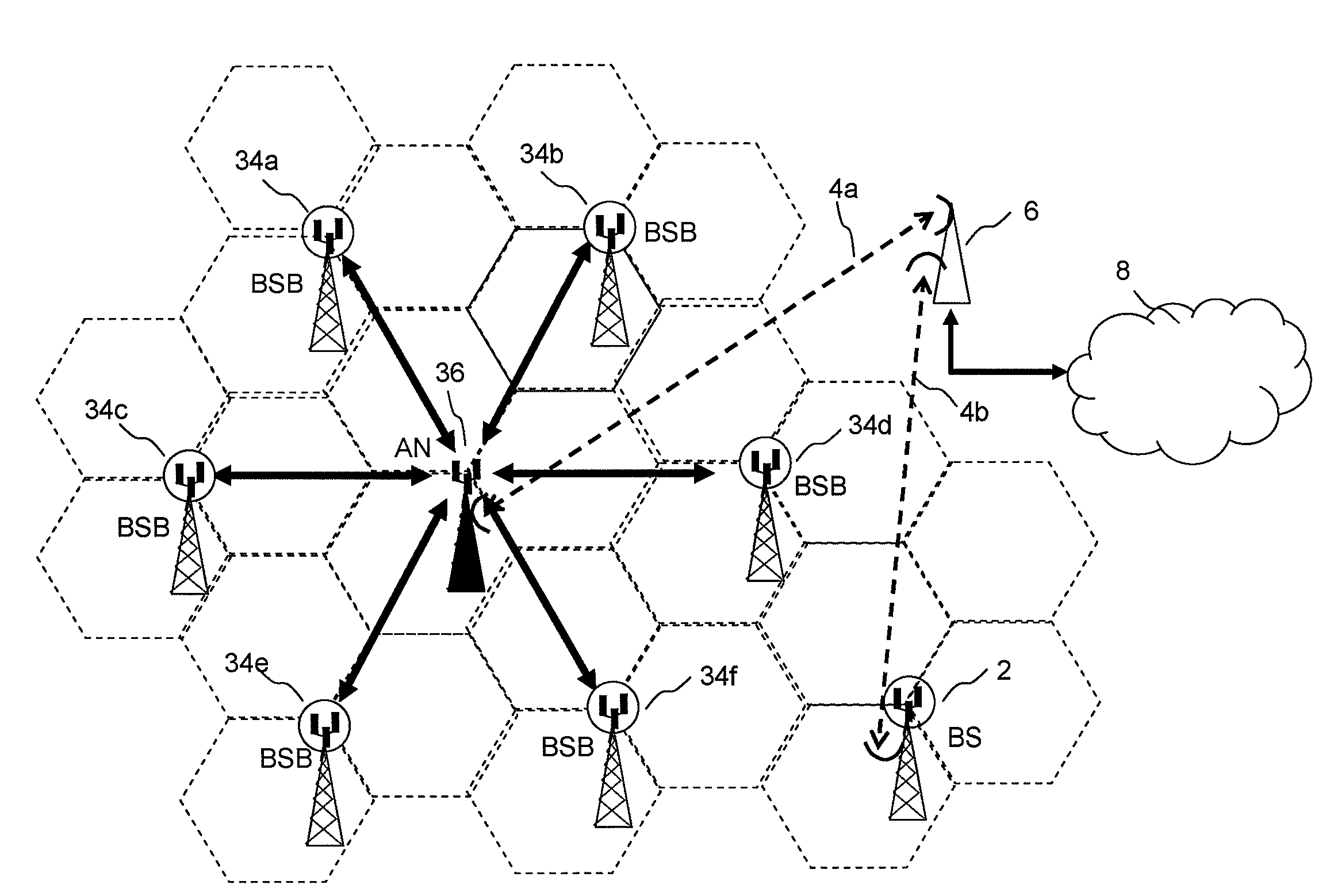
[0047]FIG. 5b shows a frame structure according to a first embodiment of the invention, and FIG. 6 illustrates connections within a wireless network that are enabled by the frame structure of FIG. 5b. FIG. 6 shows a base station 36 known as an aggregation node. This base station has a microwave backhaul link 4a to a microwave station 6 and thence to a telecommunications network 8 such as the PSTN. In this example, six base stations 34a . . . 34f known as base stations with backhaul (BSB) are connected to the aggregation node (AN) by means of ...


PUM


Abstract

Embodiments of the invention relate to wireless communications networks, and more specifically to method and apparatus relating to wireless backhaul for cellular wireless systems. Increasing data capacity of cellular wireless systems places increasing demands on the capacity of the two way connection, known as backhaul, between a cellular base station and a telecommunications network such as the PSTN backhaul, since this is the connection that has to convey the wireless-originating traffic to its destination, often in an entirely different network. Known backhaul links include leased lines, microwave links, optical fibre links or radio resources for relaying backhaul traffic between base stations. The fixed line solutions are expensive to implement and maintain, while the radio solutions suffer from interference from transmissions between base stations with transmissions from user equipment to base stations which are not communicating with other base stations. In embodiments of the invention, the relaying of access data between base stations utilises radio resources other than radio resources used by transmissions from user equipment within an area of contiguous wireless coverage. The benefit of this approach is that it provides a means of avoiding interference between inter-base station transmissions and user equipment to base station transmissions.

Description

FIELD OF THE INVENTION[0001]The present invention relates generally to wireless communications networks, and more specifically to method and apparatus relating to wireless backhaul for cellular wireless systems.BACKGROUND OF THE INVENTION[0002]Mobile telephony systems, in which user equipment such as mobile handsets communicate via wireless links to a network of base stations connected to a telecommunications network, have undergone rapid development through a number of generations. The initial deployment of systems using analogue modulation has been superseded by second generation digital systems, which are themselves currently being superseded by third generation digital systems such as UMTS and CDMA. Third generation standards provide for a greater throughput of data than is provided by second generation systems; this trend is continued with the proposal by the Third Generation Partnership Project of the so-called Long Term Evolution system, often simply called LTE, which offers ...

Claims


Application Information

Patent Timeline
Patent Type & Authority Applications(United States)
IPC IPC(8): H04J3/06H04Q7/20H04Q7/00H04W48/16H04W74/04H04W84/04H04W92/20
CPCH01Q1/246H04W48/16H04W74/04H04W88/06H04W92/20H04W88/10H04B1/0064H04W84/042
Inventor GALE, SIMONURQUHART, ANDREWNADEN, JAMES MARK
Owner APPLE INC
Why Eureka
Try Eureka