Method and device for reducing axial thrust and radial oscillations and rotary machines using same

a technology of axial thrust and radial oscillation, which is applied in the direction of machines/engines, stators, liquid fuel engines, etc., can solve the problems of general failure of the machine, excessive axial load is especially harmful to the axial thrust bearing, and the reliability of the rotary machine operation

Active Publication Date: 2008-07-31
TECH COMMLIZATION
View PDF9 Cites 13 Cited by
  • Summary
  • Abstract
  • Description
  • Claims
  • Application Information

AI Technical Summary

Problems solved by technology

Depending on the rotational speed, rotor diameter, fluid dynamics, angular gap leakage flows and many other parameters, the axial thrust may reach such significant levels so as to present a challenge to reliability of the rotary machines operation.
Excessive axial load is especially harmful for the axial thrust bearings.
Failure of the axial thrust bearing can cause general failure of the machine.
Expensive procedures of bearing replacement comprise a significant part of the overall maintenance of rotary machines, especially turbojet engines and similar machines in which access to the axial bearings is quite difficult.
As the seals wear out, the annular gap leakage flow increases, which unfavorably changes the pressure in the cavities between the rotor and the shroud of the rotary machine and typically causes an increase in the axial thrust.
That in turn causes higher yet axial loads on the axial thrust bearings and may bring about their premature failure.
Such variations in axial position of the rotor impact various operating parameters of the pump or compressor, reducing potential machine efficiency and most likely negatively impacting rotor-dynamic stability.
Fluid-induced instability can occur whenever a flu...

Method used


Image

  • Method and device for reducing axial thrust and radial oscillations and rotary machines using same
  • Method and device for reducing axial thrust and radial oscillations and rotary machines using same
  • Method and device for reducing axial thrust and radial oscillations and rotary machines using same

Examples


first embodiment

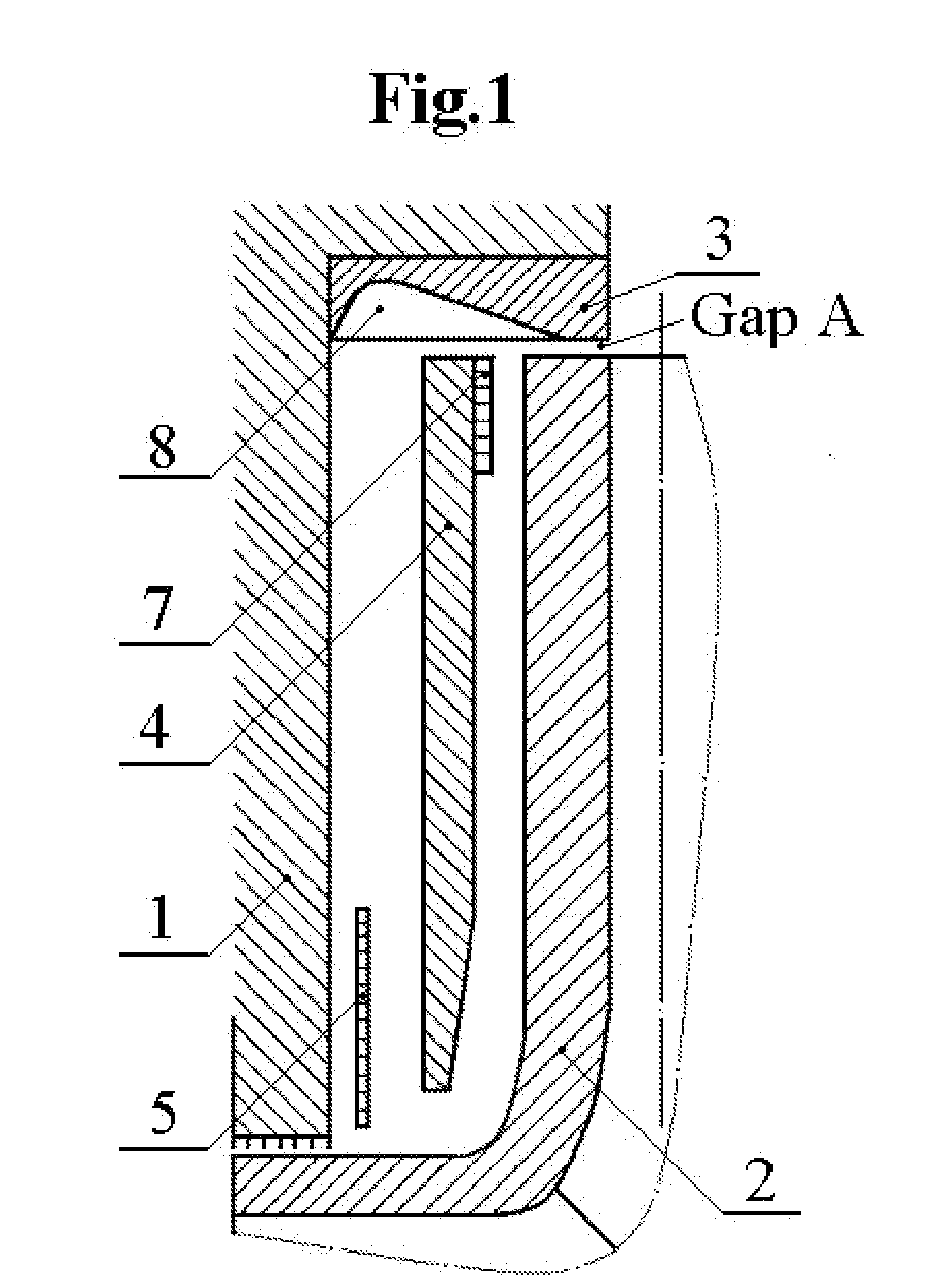
Design Features of the Invention as Shown on FIG. 1

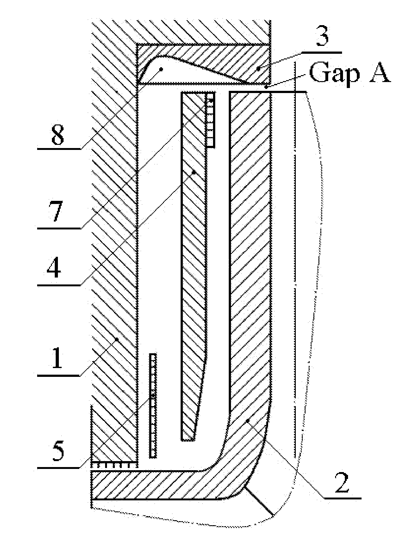
[0051]In FIG. 1, rotating rotor (2) induces outward rotating flow of the adjacent fluid, which then enters the peripheral vane system (8). Such flow, combined with leakage flow through the annular gap at the periphery of rotor (2) (Gap A), having tangential momentum, is redirected by peripheral vanes (8) into radially inward flow directed toward hub between the stator (1) and subdividing means (4). Stator (1) is assumed to be a part of the housing shroud of the rotary machine. Radial ribs (not shown) may be used to attach subdividing means (4) and additional optional radial disc (5) to stator (1) and to further condition flow. The purpose for the optional radial disc (5) is to assist in improving flow conditions (preferably, reverse direction to shaft using anti-rotation vanes, not shown) for leakage flow entering shaft seal.

[0052]An important feature shown in FIG. 1 is that subdividing means (4) is designed to separate the flow in ...

second embodiment

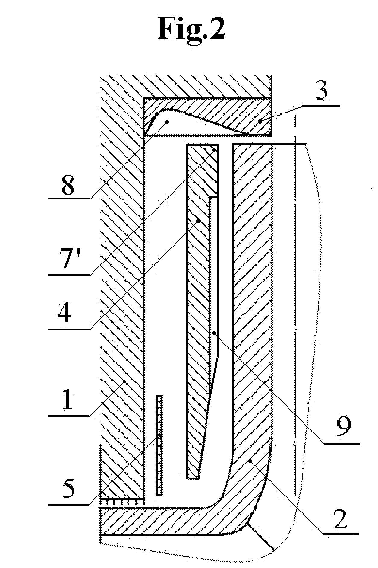
Design Features of the Invention as Shown on FIG. 2

[0059]Many design elements of FIG. 1 are incorporated into FIG. 2. The primary difference is that raised ring-shaped restrictive means (shown as position 7 in FIG. 1) has been removed, and that spiral grooves (9) (or vanes, wavy surface, Rayleigh steps, etc.) have been cut into the subdividing means (4) on the side facing the rotating rotor. Such spiral grooves (as shown) do not extend all the way to the outer perimeter of the subdividing means (4) therefore forming an outer ring face section (7′) (the landing area) that functions as a peripheral restrictive means (such as the dam of hydrodynamic ring seals), where the high pressure produced by the spiral grooves results in lift at the leading edge of restrictive means (7′), providing separation forces between the two opposing faces. Compared to the design in FIG. 1, the design features of FIG. 2 allow for increasing / improving axial stiffness and damping characteristics. The periphe...

third embodiment

Design Features of the Invention as Shown on FIG. 3

[0060]Many design elements of FIG. 2 are incorporated into FIG. 3. The primary difference in FIG. 3 is that radial ribs such as spiral grooves (9′) and restrictive means (7″) are placed on the face of rotating rotor (2), not on stationary subdividing means (4). Such placement on the peripheral restrictive means on the rotating rotor is especially beneficial when the working fluid has low viscosity (such as gases or cryogenic liquids), and when additional performance is desired (increased thrust or increased fluid stiffness).


PUM


Abstract

A method and apparatus to reduce the axial thrust in rotary machines such as compressors, centrifugal pumps, turbines, etc. includes providing additional peripheral restrictive means (7) attached at the peripheral portion of the disk forming the subdividing means (4) on the side facing the rotating rotor (2). An additional ring element at the periphery of the subdividing means forms additional radial (11) and axial restrictive means (15). Such peripheral restrictive means (7, 11 and 15) function as sealing dams, which combined with the outward flow induced by the rotating impeller, form self-pressurizing hydrodynamic bearings in the axial and radial planes, improving rotordynamic stability. Additionally, a stationary ring element in the center of the cavity forms a seal with the rotor, reducing leakage to suction.

Description

BACKGROUND OF THE INVENTION[0001]1. Field of the Invention[0002]The present invention relates to a method and device for reducing or eliminating axial thrust, axial oscillations and radial oscillations of the rotor commonly associated with rotary machines. The term “rotary machines” for the purposes of this description includes centrifugal, axial, turbo- and other pumps, compressors, pneumatic and hydraulic turbines and motors, turbine engines, micro-compressors and micro-pumps, MEMS, jet engines and other similar machines. More specifically, the present invention relates to rotary machines having a stationary subdividing disc (subdividing means) located in the cavity between the rotor and the housing for the purpose of changing the nature of the flow dynamics and the pressure distribution along the outside of the rotor (between the stationary subdividing means and the rotor), and creating a hydrostatic / hydrodynamic self-pressurized axial / radial bearing as a functional unit consisti...

Claims


Application Information

Patent Timeline
IPC IPC(8): F01D3/00F04D29/00
CPCF01D3/00F01D11/02F04D29/041F05D2240/53F04D29/051F04D29/056F05D2240/52F04D29/046F04D29/0416F04D29/0513F04D29/0413
Inventor GANELIN, BORIS Y.KENWORTHY, MICHAEL W.
Owner TECH COMMLIZATION
Why Eureka
Try Eureka