

Integrated leading edge for wind turbine blade
- Summary
- Abstract
- Description
- Claims
- Application Information
AI Technical Summary
Benefits of technology
Problems solved by technology
Method used
Image

Examples
Embodiment Construction
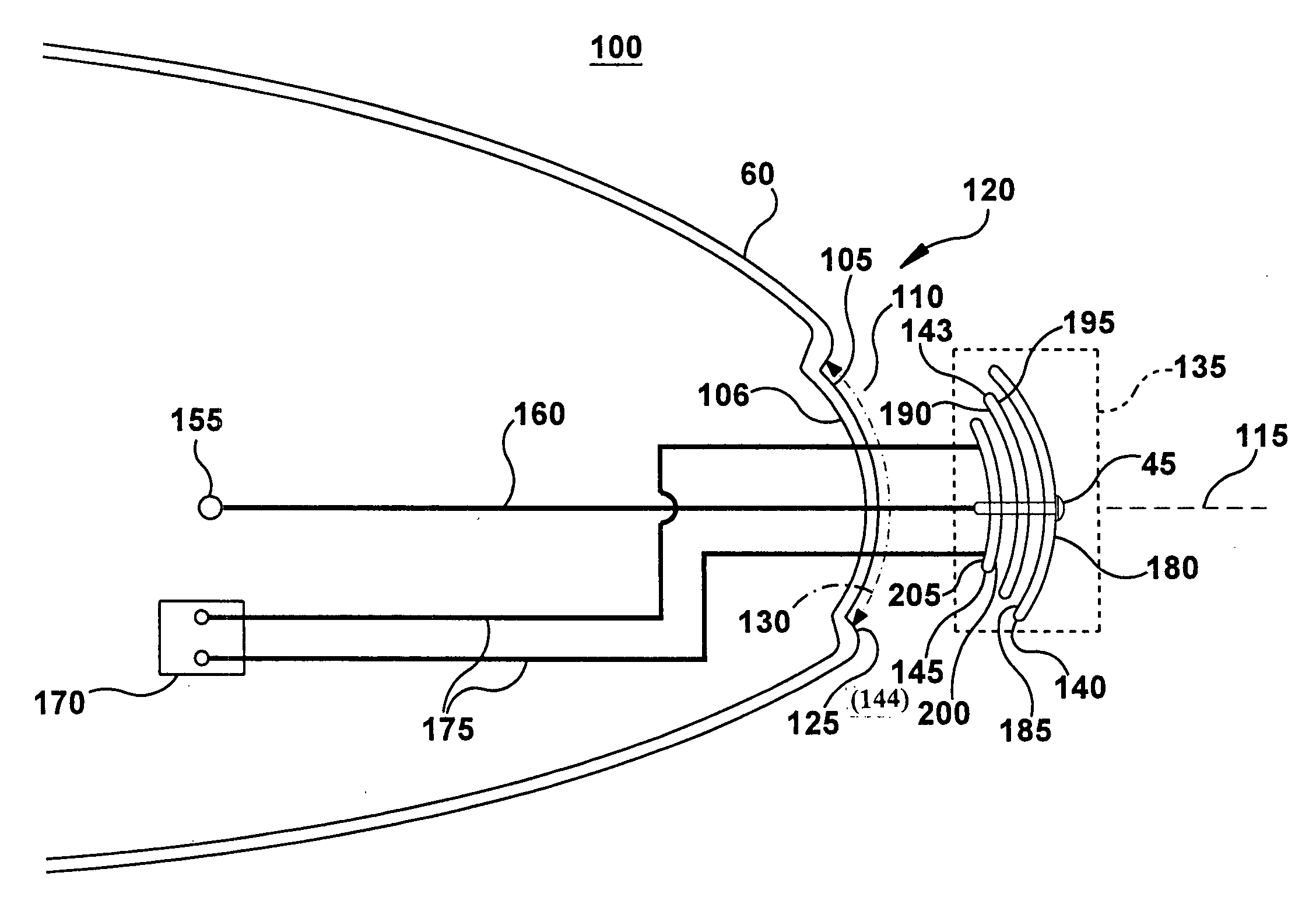
[0024]The following embodiments of the present invention have many advantages, including providing an integrated protection system for the leading edge of the wind turbine blade against erosion, lightning strikes and icing. The protection system includes an erosion shield with aerodynamic properties, which protects the leading edge against erosion and further serves as a lightning receptor and conveyor, and a heat-generating source for deicing or preventing icing on the leading edge.
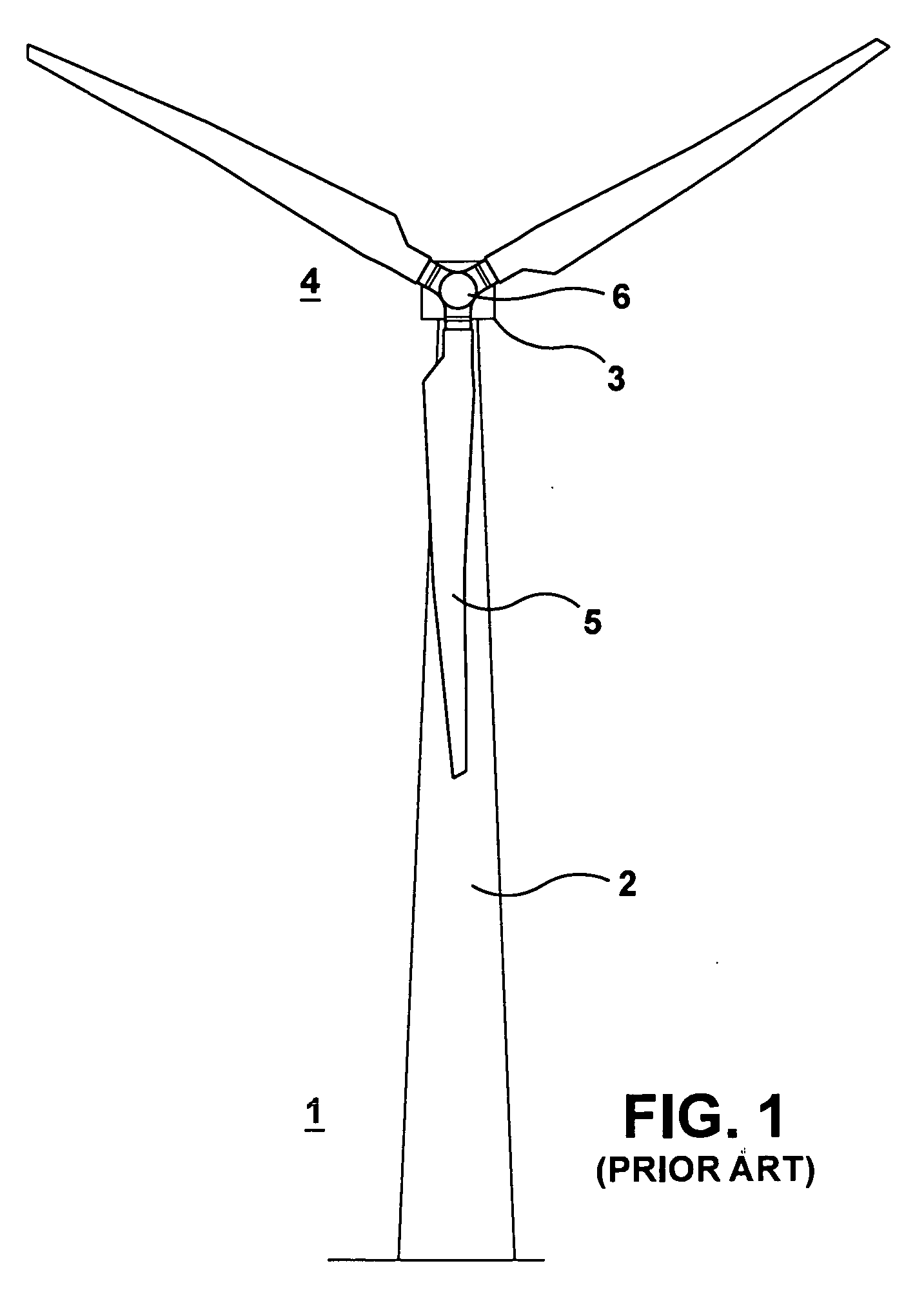
[0025]FIG. 1 illustrates a typical structure for a wind turbine. The wind turbine 1 includes a support tower 2, and a wind turbine nacelle 3 mounted on the support tower 2. The nacelle 3 houses the electrical generator (not shown) and gearbox (not shown) and supports a rotor shaft (not shown) extending from the gear box. The wind turbine rotor 4, mounted on the rotor shaft, supports three wind turbine blades 5 through a hub 6.
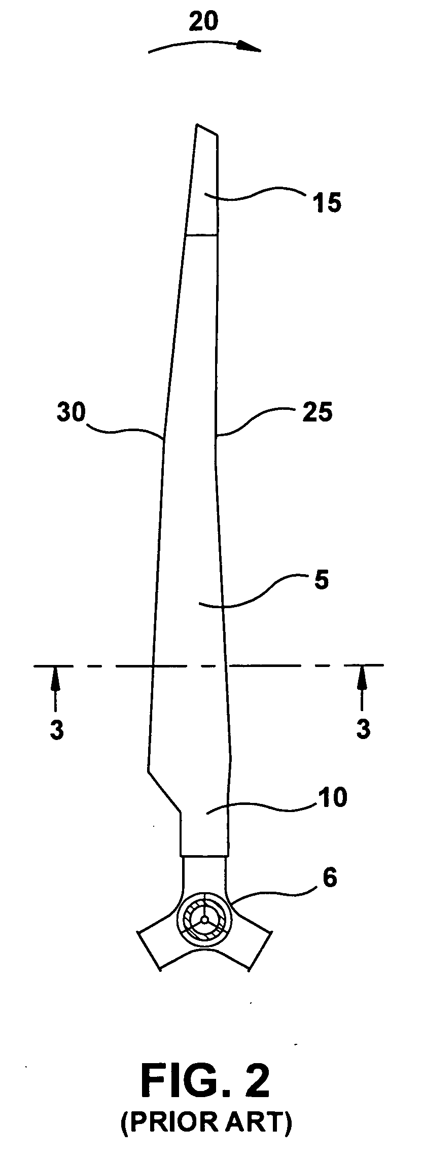
[0026]FIG. 2 illustrates a typical structure for a wind turbine blade. The blad...
PUM
 Abstract
Description
Claims
Application Information