

Surface luminous body, manufacturing method of the same, display device and illuminating device using the same
a technology of surface luminous body and manufacturing method, which is applied in the direction of optics, thin material handling, instruments, etc., can solve the problems of difficult inability to obtain sufficient front brightness, and inability to achieve front brightness of 1000 to 1500 cd/msup>2 or so, and achieves convenient hand-accessibility, small thickness, and easy to view
- Summary
- Abstract
- Description
- Claims
- Application Information
AI Technical Summary
Benefits of technology
Problems solved by technology
Method used
Image

Examples
embodiment 1
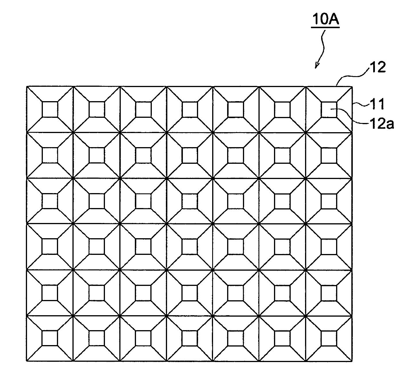
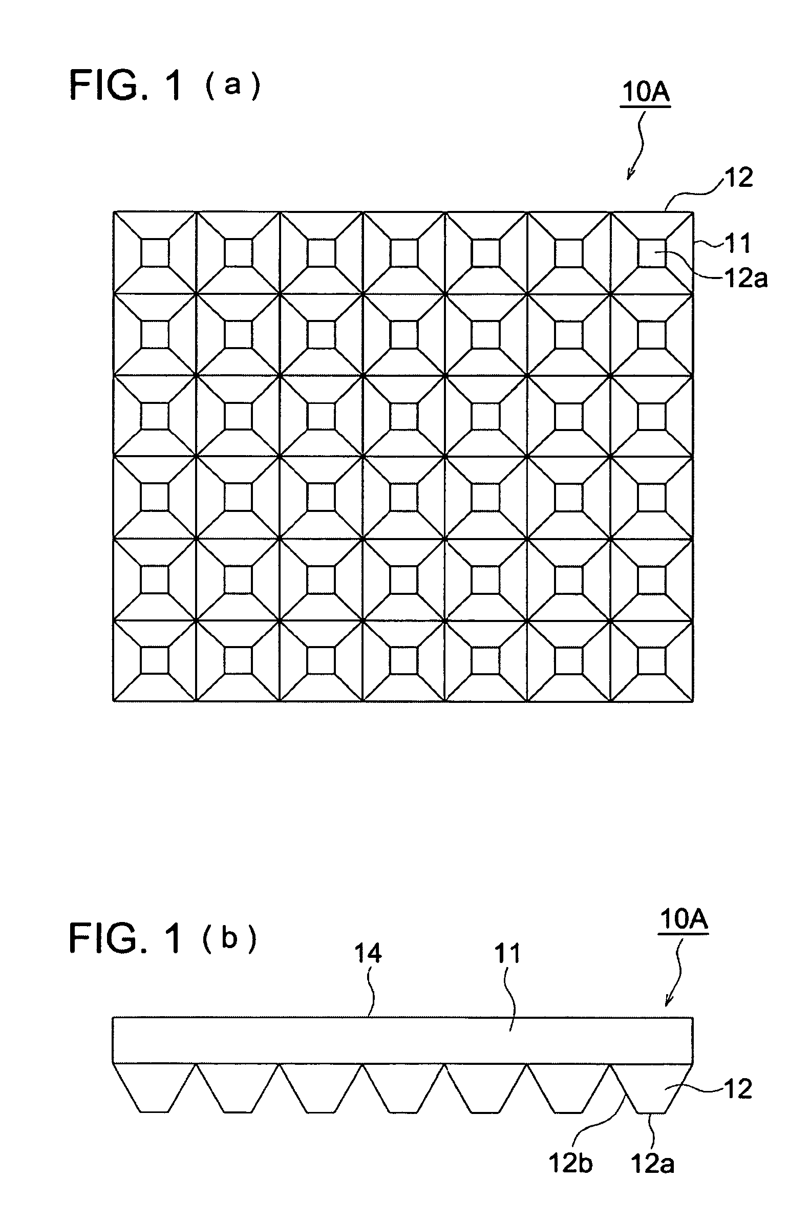
[0065]In Embodiment 1, as a light regulating sheet, as shown in FIGS. 1(a) and (b), a prism array sheet 10A composed of protrusions 12 in the truncated quadrangular pyramid shape having a contracted end side which are continuously formed lengthwise and crosswise on one side of a light transmissive substrate 11 is used. Further, in this specification, contraction of the end side of the protrusions 12 means that the protrusions 12 become gradually smaller as they go away from the prism array sheet 10A and in the examples shown in FIG. 1(b) and FIGS. 2 to 10 which will be described later, is tapered off.
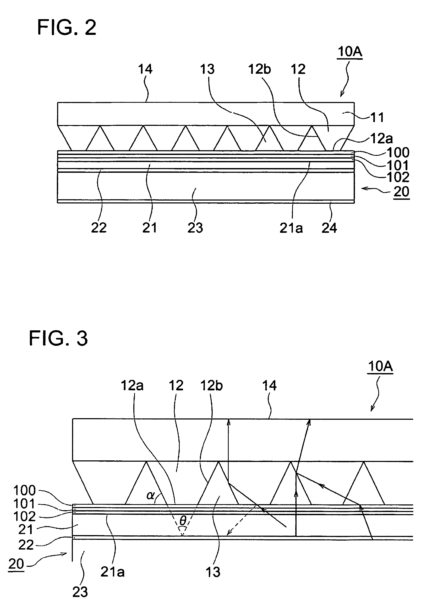
[0066]And, in the surface luminous body of Embodiment 1, as shown in FIG. 2, a surface luminous element 20 composed of an organic EL element in which on the surface of a transparent substrate 21 having an installed transparent electrode 22, an organic EL layer 23 and an opposite electrode 24 are installed is used. Onto a light outgoing surface 21a of the transparent substrate 21 from wh...
embodiment 2
[0081]In Embodiment 2, as shown in FIG. 7, on the light outgoing surface 21a of the surface luminous element 20, the adhesion layer composed of the transparent pressure-sensitive adhesion layer 102 and transparent pressure-sensitive adhesion layer 100 and the prism array sheet 10A are laminated in this order and the end faces 12a of the protrusions 12 of the prism array sheet 10A, pressure-sensitive adhesion layer 100, pressure-sensitive adhesion layer 102, and light outgoing surface 21a of the surface luminous element 20 are structured so as to be adhered optically closely. To be more specific, as shown in FIG. 8, the neighborhood of the end faces 12a of the protrusions 12 of the prism array sheet 10A is formed so as to be embedded in the adhesion layer composed of the pressure-sensitive adhesion layer 100 and pressure-sensitive adhesion layer 102. The adhesion layer composed of the pressure-sensitive adhesion layer 100 and pressure-sensitive adhesion layer 102 and the protrusions ...
embodiment 3
[0082]In Embodiment 3, as shown in FIG. 9, on the light outgoing surface 21a of the surface luminous element 20, the adhesion layer composed of the transparent pressure-sensitive adhesion layer 100 and the prism array sheet 10A are laminated in this order and the end faces 12a of the protrusions 12 of the prism array sheet 10A, pressure-sensitive adhesion layer 100, and light outgoing surface 21a of the surface luminous element 20 are structured so as to be adhered optically closely. To be more specific, as shown in FIG. 10, the neighborhood of the end faces 12a of the protrusions 12 of the prism array sheet 10A is formed so as to be embedded in the adhesion layer composed of the pressure-sensitive adhesion layer 100. The adhesion layer composed of the pressure-sensitive adhesion layer 100 and the protrusions 12 of the prism sheet are selected so as to have almost the same refractive index, so that the width of the prism array sheet 10A where it is adhered optically closely with the...
PUM
| Property | Measurement | Unit |
|---|---|---|
| Fraction | aaaaa | aaaaa |
| Thickness | aaaaa | aaaaa |
| Sensitivity | aaaaa | aaaaa |
Abstract
Description
Claims
Application Information