Clock circuitry architecture to improve electro-magnetic compatibility and optimize peak of currents in micro-controller

Active Publication Date: 2008-07-31
ATMEL CORP
View PDF6 Cites 7 Cited by
  • Summary
  • Abstract
  • Description
  • Claims
  • Application Information

AI Technical Summary

Benefits of technology

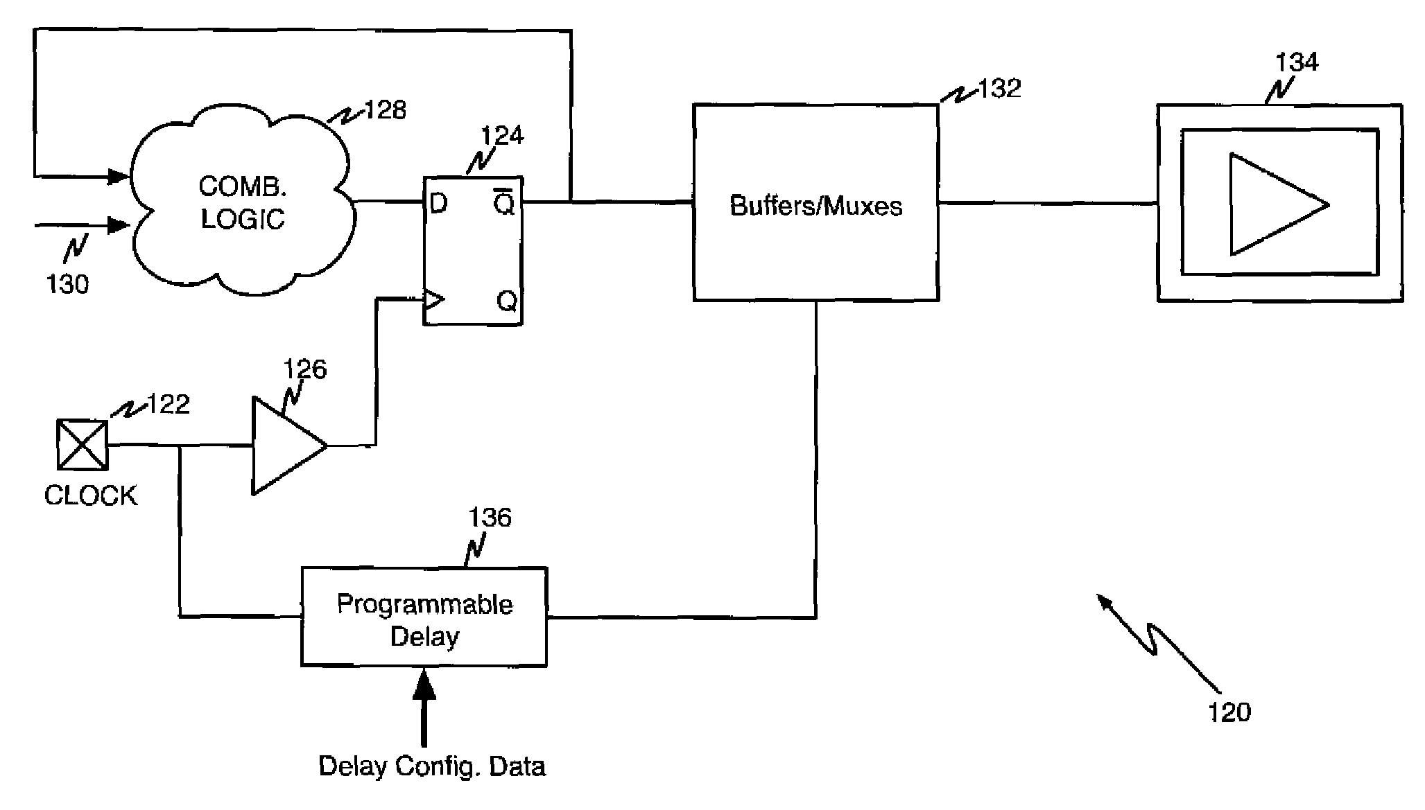
[0030]Therefore there is a need for adjustable delay to guaranty optimal EMC compatibility whatever the clock frequency is. A programmable level of adjustable delay to p

Problems solved by technology

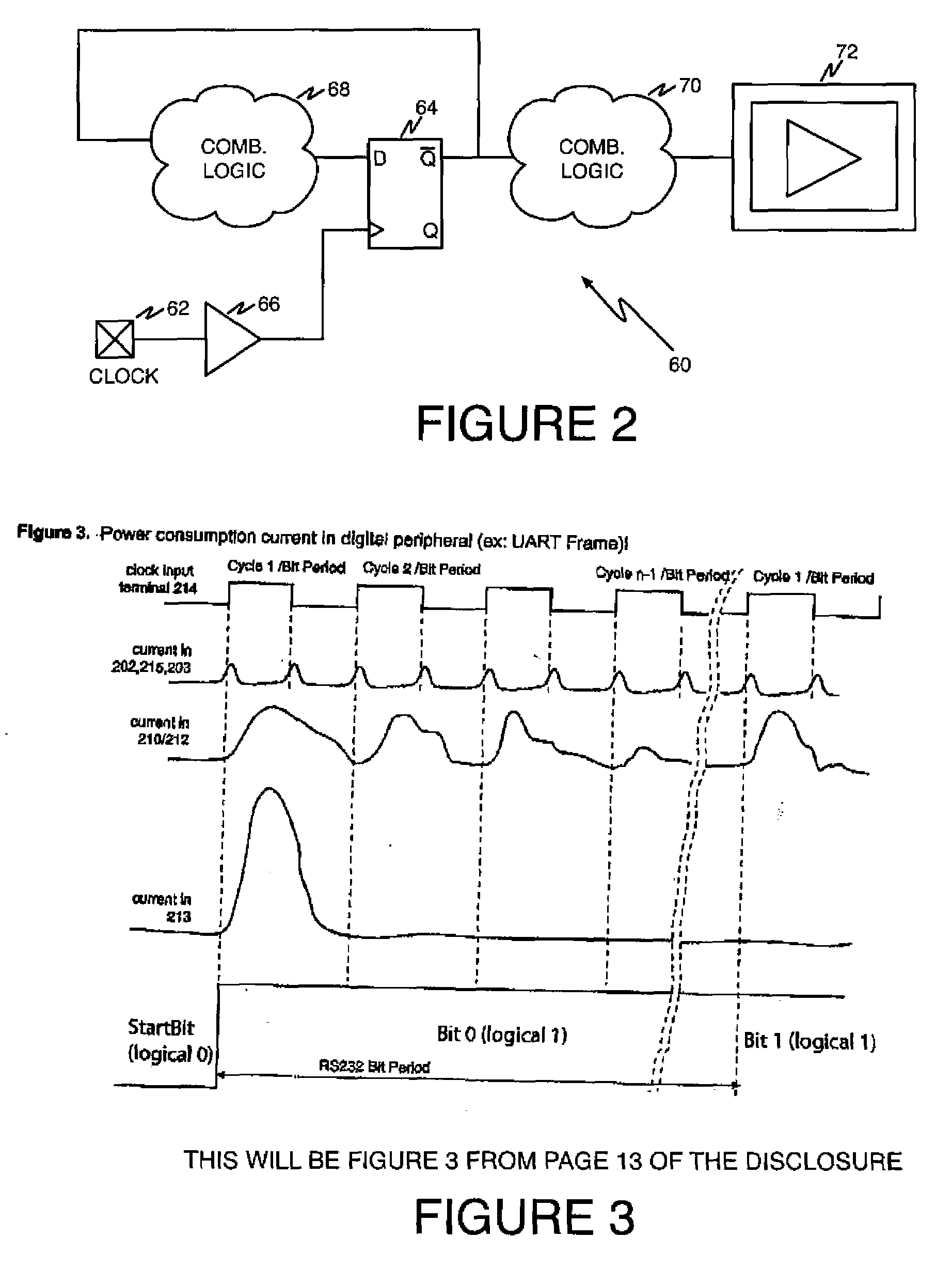
All of the modules of a micro-controller are often clocked by the same clock signal, causing a peak in the power consumption for each active edge of the clock signal due to the switching of sequential cells and to the combinational logic networks driven by the sequential cells.
The software application code would be difficult to generate without interrupt handling in a micro-controller system having several modules with different latencies.
The parity bit may be calculated in serial mode (for each bit time, a 1 bit counter is toggling according to the transmitted bit value) or in parallel using more combinatorial cells (XOR) to compute parity when the data to transmit is loaded into a register, resulting in a different power consumption current.
Another factor of noise on lines is the current slew rate.
The power supply lines are also capacitive, and, when logic is switching, the induced voltage parasitic induced can propagate on the power supply lines of the integrated circuit and may interfere with the other circuits powered on the same supply of the printed circuit board.
Yet another potential source of interference is the electromagnetic propagation that may occur due to different lengths of internal nets such as power supply lines, in combination with different parasitic capacitors and inductances.
The second factor may not easy to adjust because it partially depends on the architecture of the logic of the particular peripherals embedded in the micro-controller.
Once manufactured, it is no longer possible to modify it.
Such a solution, however, requires more DFFs to obtain the equivalent function, resulting in higher power consumption current and a larger number of clock cycles to perform the data processing.
If a single peripheral is processing data into a micro-controller it is difficult to get improvement in di / dt (current slope) because the architecture of the peripheral logic is pre-determined.
One drawback of this method is that the delay value may not be optimal for all cases of use.
By unbalancing the terminal clock of each module of the micro-controllers, the current peaks of the modules may add together in a less destructive manner for EMC, resulting in a limited current peak compared to a full balanced clock circuit.
This is true for the peak current due to sequential cells, but the shape of the current resulting from the combinational logic is more complex and a fixed unbalancing may result to higher current peaks.
Fixed unbalancing of internal clocks of same frequency is used especially in some integrated circuits for the automotive market where the electromagnetic compatibility must be improved but the unbalancing delay is limited by the maximum acceptable clock frequency of the circuit.
The lower the clock frequency, the larger the clock period, therefore delay margins are larger at low frequencies and higher unbalancing may be performed.

Method used


Image

  • Clock circuitry architecture to improve electro-magnetic compatibility and optimize peak of currents in micro-controller
  • Clock circuitry architecture to improve electro-magnetic compatibility and optimize peak of currents in micro-controller
  • Clock circuitry architecture to improve electro-magnetic compatibility and optimize peak of currents in micro-controller

Examples


Embodiment Construction

[0044]Persons of ordinary skill in the art will realize that the following description of the present invention is illustrative only and not in any way limiting. Other embodiments of the invention will readily suggest themselves to such skilled persons.

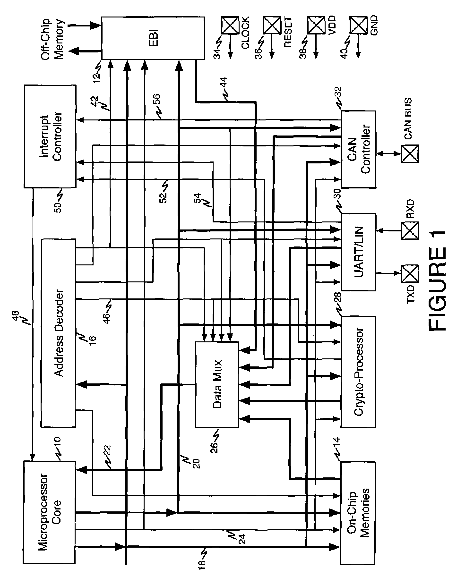
[0045]The present invention finds application in the area of micro-controller integrated circuit devices but can be used in any other type of circuits where digital logic modules are embodied. The present invention may be advantageously employed in a crypto-processor digital module but can be used in any other digital module. Crypto-processor modules can be mainly found in micro-controller integrated circuits but also in any other type of integrated circuits. The disclosure of the present invention will be given for the illustrative example of a micro-controller, but persons of ordinary skill in the art will readily understand from the present disclosure how the invention may be employed in other systems.

[0046]Referring now to FIG. 6,...


PUM


Abstract

A system comprises a central processing unit and a set of peripheral units accessible by the CPU and being able to be driven by the same clock source. At least one programmable delay line is located in the clock branch of one of the peripheral units and has a delay selection input that is accessible by software running on the system.

Description

BACKGROUND OF THE INVENTION[0001]1. Field of the Invention[0002]The present invention relates to digital logic systems employing combinatorial and sequential logic, such as microcontroller systems. More particularly, the present invention relates to a clock circuitry architecture that employs tunable variable delays for use in such systems.[0003]2. The Prior Art[0004]To improve the effectiveness of micro-controller systems with respect to the volume of information to be processed, co-processor modules are connected the central processing unit through the internal system bus. The co-processor modules can be accessed for configuration, sending commands / data, and can be interrogated for status.[0005]All of the modules of a micro-controller are often clocked by the same clock signal, causing a peak in the power consumption for each active edge of the clock signal due to the switching of sequential cells and to the combinational logic networks driven by the sequential cells.[0006]Referri...

Claims


Application Information

Patent Timeline
IPC IPC(8): G06F13/00
CPCG06F1/10
Inventor VERGNES, ALAINDUPRE, LUDOVICDUMAS, DAVID
Owner ATMEL CORP
Why Eureka
Try Eureka