Non-linear distortion detection method and distortion compensation amplifying device

a non-linear distortion and detection method technology, applied in the direction of amplifier modification, pulse manipulation, pulse technique, etc., can solve the problems of increasing circuit size, interfering with another radio equipment, interfering with intermodulation distortion of transmission signals, etc., and achieves enhanced stability of convergence and high precision.

Inactive Publication Date: 2008-08-07
KOKUSA ELECTRIC CO LTD
View PDF6 Cites 74 Cited by
  • Summary
  • Abstract
  • Description
  • Claims
  • Application Information

AI Technical Summary

Benefits of technology

[0071]Besides, the invention consists in the distortion compensation amplifying device characterized in that the predistorter is a predistorter which includes a third-order intermodulation distortion generator, a fifth-order intermodulation distortion generator, a seventh-order intermodulation distortion generator, a first FIR filter corresponding to the third-order intermodulation distortion generator, a second FIR filter corresponding to the fifth-order intermodulation distortion generator, and a third FIR filter corresponding to the seventh-order intermodulation distortion generator; and that the control unit is a control unit which updates tap coefficients of the first, second and third FIR filters of the predistorter on the basis of the distortion v

Problems solved by technology

However, the intermodulation distortions of a transmission signal appear on account of the non-linearity of the power amplifier, and they interfere with another radio equipment.
Further, as the band of the signal widens more, the sampling frequency needs to be raised in the A/D converter (A/D converter 9 in FIG. 8) for detecting the distortion, and a calculation amount in the FFT calculation portion of

Method used


Image

  • Non-linear distortion detection method and distortion compensation amplifying device
  • Non-linear distortion detection method and distortion compensation amplifying device
  • Non-linear distortion detection method and distortion compensation amplifying device

Examples


first configurational example

[0225]FIG. 21 is a block diagram showing the first configurational example of the Doherty amplifier 20. This Doherty amplifier 20 is such that the λ / 4 transformer 61 in FIG. 15 is replaced with an impedance transformer 64 formed of a transmission line of any desired electrical length, and that the phase shifter 113 is replaced with a phase shifter 31. The remaining configuration is basically the same though constants, etc. are different.

[0226]The impedance transformer 64 is formed of the transmission line which has the electrical length of length l=0−λ / 2 or above.

[0227]The phase shifter 31 is, in principle, a transmission line which generates a delay corresponding to the impedance transformer 64. The phase shifter 31 serves to perform synthesis in in-phase fashion, and it must absorb the phase difference between the carrier amplifying circuit 40 and the peak amplifying circuit 50, so that the delay thereof is sometimes different from the delay of the impedance transformer 64. The re...

second configurational example

[0229]FIG. 22 is a block diagram showing the second configurational example of the Doherty amplifier 20. This second configurational example is such that, in the Doherty amplifier 20 shown in FIG. 21, an impedance transformer 65 is interposed between the peak amplifying circuit 50 and the node 62, while the phase shifter 31 is replaced with a phase shifter 33. The remaining configuration is basically the same.

[0230]The node 62 couples output signals from the output matching circuits 43 and 53, through the impedance transformers 64 and 65. The impedance transformer 65 is formed of, for example, a transmission line of any desired length similar to the impedance transformer 64, and it transforms the output impedance of the output matching circuit 53 into a larger impedance so that, when the amplifying element 52 is not operating on account of the low level of an input signal, the signal of the carrier amplifying circuit 40 may be prevented from flowing.

[0231]The phase shifter 33 genera...

third configurational example

[0233]FIGS. 23(a) and (b) are block diagrams showing the third configurational example of the Doherty amplifier 20. This third configurational example is such that, in the Doherty amplifier 20 shown in FIG. 22, a phase shifter 34 and impedance transformers 66 and 67 are respectively used instead of the phase shifter 33 and the impedance transformers 64 and 65. The remaining configuration is basically the same.

[0234]Any of the phase shifter 34 and the impedance transformers 66 and 67 is such that a plurality of transmission lines (here, of three sorts) of different lengths and switches are combined.

[0235]The individual transmission lines have the lengths which are optimized so as to make the performance of the amplifier best, in accordance with a plurality of frequencies previously expected to be used. Besides, they are not limited to ones which are formed by providing conductor patterns on a wiring board, but they may well employ semi-rigid cables whose lengths can easily be finely ...


PUM


Abstract

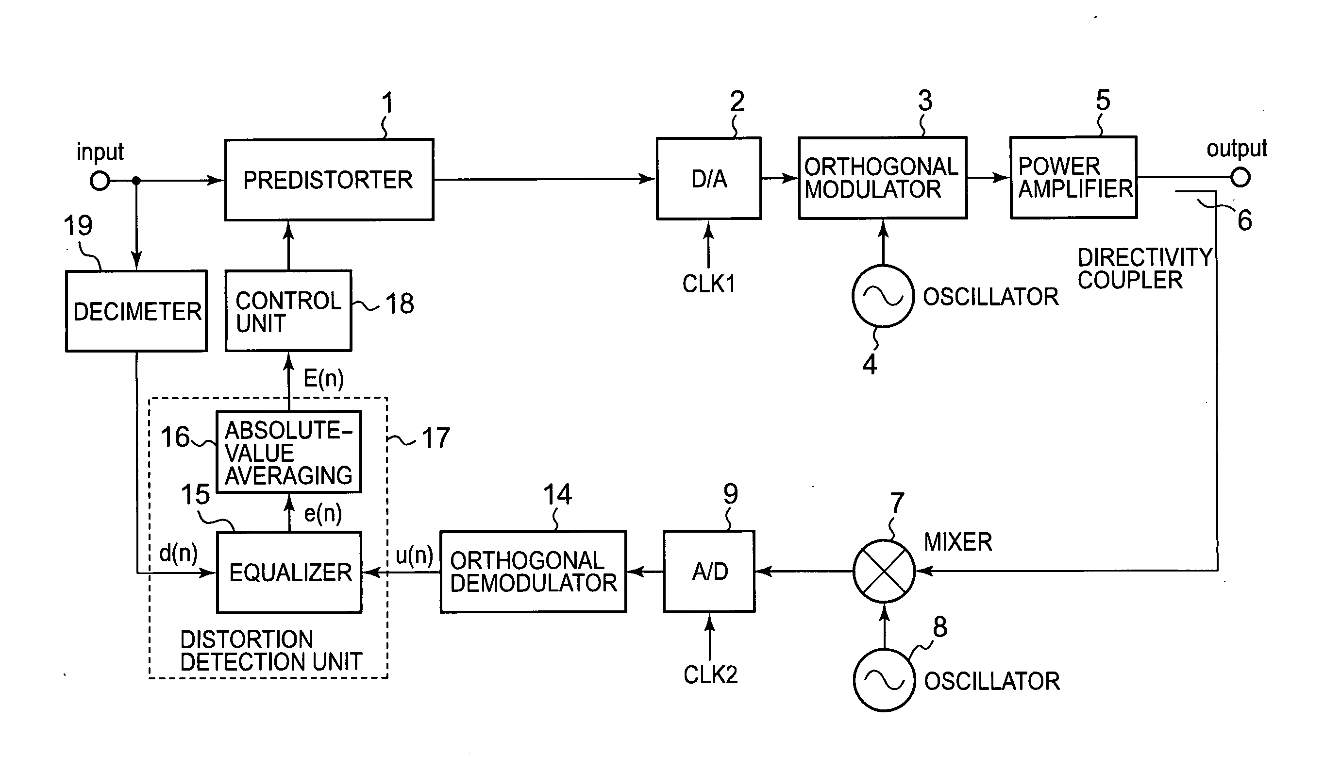
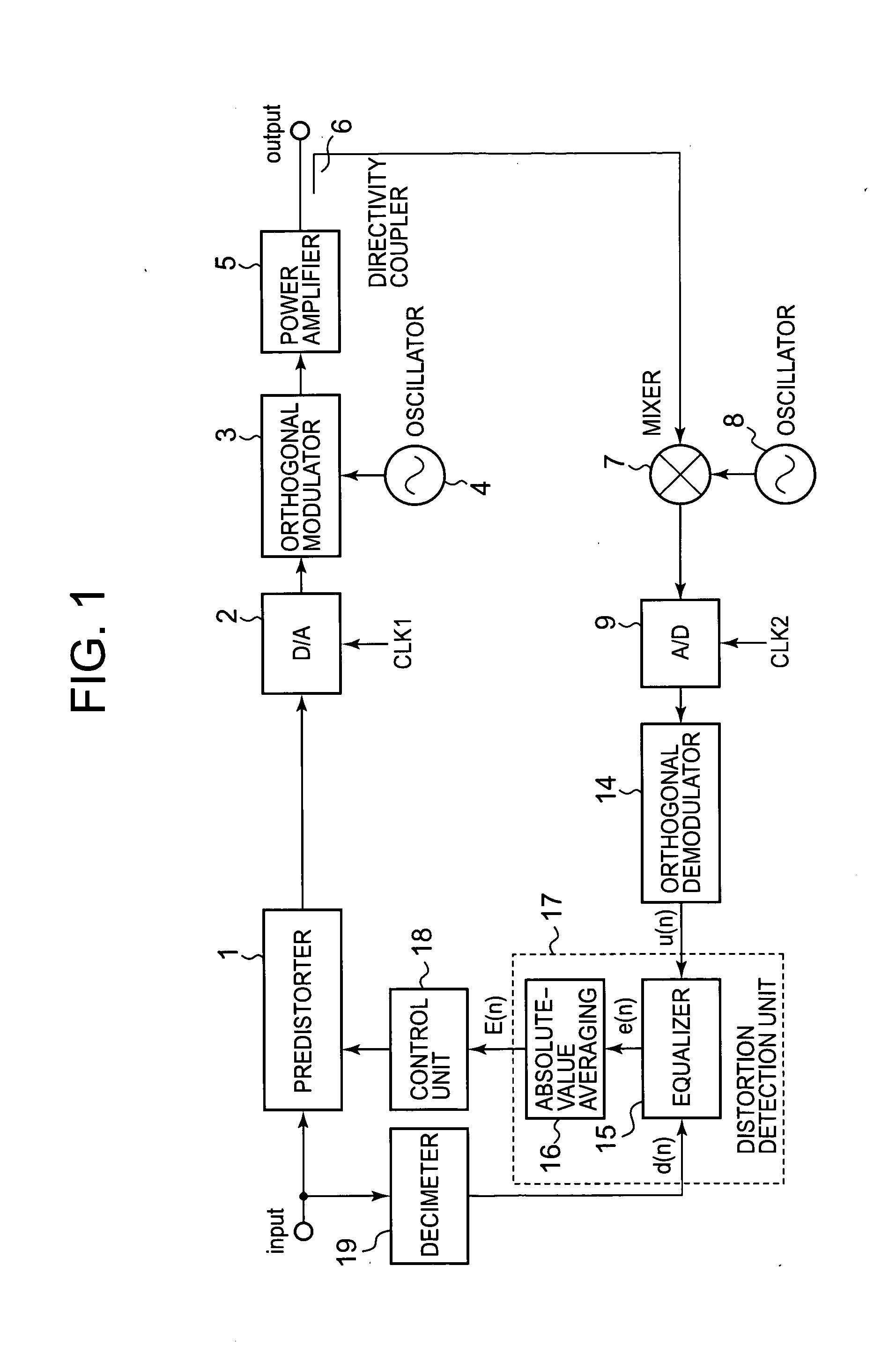
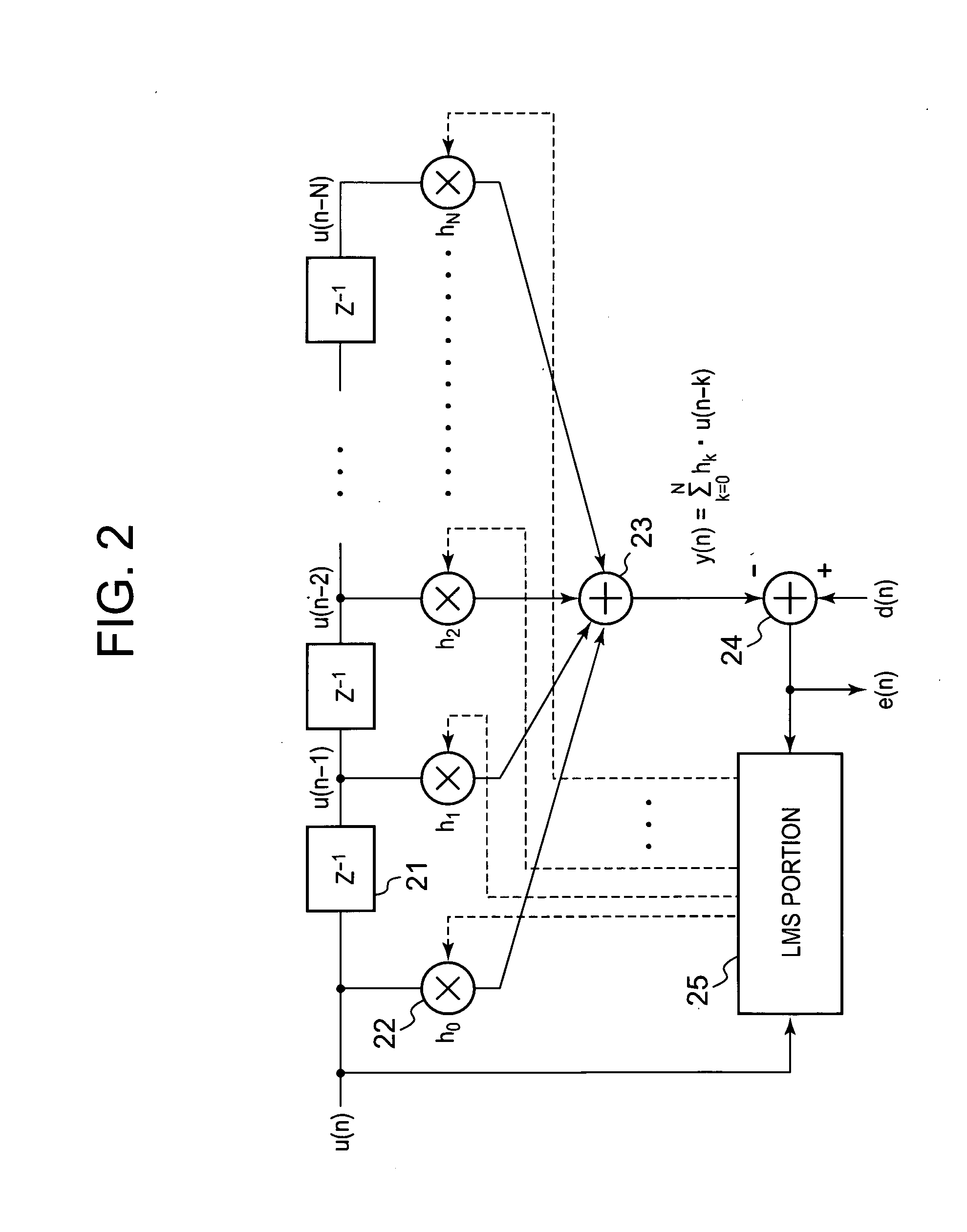
A conventional power amplifying device has a problem that when a signal band is widened, sampling frequency for distortion detection is increased and an FFT calculation amount of a distortion compensation unit is increased, which increase a circuit size and power consumption. The present invention provides a non-linear distortion detection method and a distortion compensation amplifying device capable of suppressing increase of the circuit size and the power consumption even if the signal band is widened. A signal obtained by feeding back an output of a power amplifier is sampled by an A/D converter. An equalizer of a distortion detection unit uses an input signal d(n) of a predistorter as a reference symbol to detect an equalization error e(n) of the orthogonal demodulation signal u(n). An absolute value averaging unit outputs an absolute value of the equalization error e(n) which has been temporally averaged to E(n) as a distortion value to a control unit. According to the distortion value, the control unit adaptively controls the predistorter to perform distortion compensation.

Description

BACKGROUND OF THE INVENTION[0001]1. Field of the Invention[0002]The present invention relates to a non-linear distortion detection method which detects a non-linear distortion in the power amplifier of a radio communication transmitter, and a distortion compensation amplifying device which compensates the non-linear distortion, and more particularly to a non-linear distortion detection method and a distortion compensation amplifying device in which, even if the band of a modulation signal is widened, a sampling frequency need not be heightened, and distortion detection can be performed without increasing a circuit size and dissipation power.[0003]2. Description of the Related Art[0004]Consideration for an environment, the decrease of consumption power, the decreases of a size and a weight, etc. have been required of a power amplifier in a transmission apparatus, and in order to meet these requirements, it has become necessary to attain a higher efficiency by decreasing thermal radia...

Claims


Application Information

Patent Timeline
IPC IPC(8): H04L27/01H03F1/32
CPCH03F1/0288H03F1/32H03F2200/207H03F3/245H03F1/3247
Inventor NAKAMURA, MANABUTAKEDA, YASUHIROOKUBO, YOICHIADACHI, MASARUHONGO, NAOKI
Owner KOKUSA ELECTRIC CO LTD
Why Eureka
Try Eureka