
Data communications system and data communications method

a data communication and data communication technology, applied in the field of data communication systems and data communication methods, can solve the problems of increasing the memory of other stations in proportion to the capacity, the delay time (latency) of reflected data written, etc., to avoid data collision without increasing the load of data communication, and the utilization efficiency of the bus

Inactive Publication Date: 2008-08-07
HITACHI LTD
View PDF8 Cites 7 Cited by
  • Summary
  • Abstract
  • Description
  • Claims
  • Application Information

AI Technical Summary

Benefits of technology

[0009]In the above-mentioned conventional method, the load of the software becomes none by making the communication process of the serial bus to be performed by hardware and the communication latency becomes clear by that the copy cycle of the memory data is fixed. However, as the method makes the memory data of all the stations be consistent by periodically transmitting all the memory data shared between the plurality of stations on the serial bus, there is a problem that the delay time (latency) to reflect the data written in the memory of a certain station to the memory of other stations increases in proportion to the capacity of the memories which share the data.
[0010]The present invention has been invented taking these points into consideration and it aims at realizing a data communications system which realizes at the same time (1) to have the small worst latency of the communication not being affected from the amount of the shared data being large or small, and to realize the fast communication speed, (2) to have the small software load of the processor, and (3) to adopt the serial connection method which has small wiring amount and is advantageous to the small space mounting.
[0032]In the present invention, it is possible to avoid the data collision without increasing the load to the data communications of the serial bus by performing the transfer of the transmission right providing the communication control lines between the plurality of processing devices connected by the serial bus. By avoiding the data collision which is the cause to deteriorate the utilization efficiency of the bus, the effective data communication speed is enhanced and at the same time the data retransmission process does not occur and it is possible to make the worst latency of the communication small.
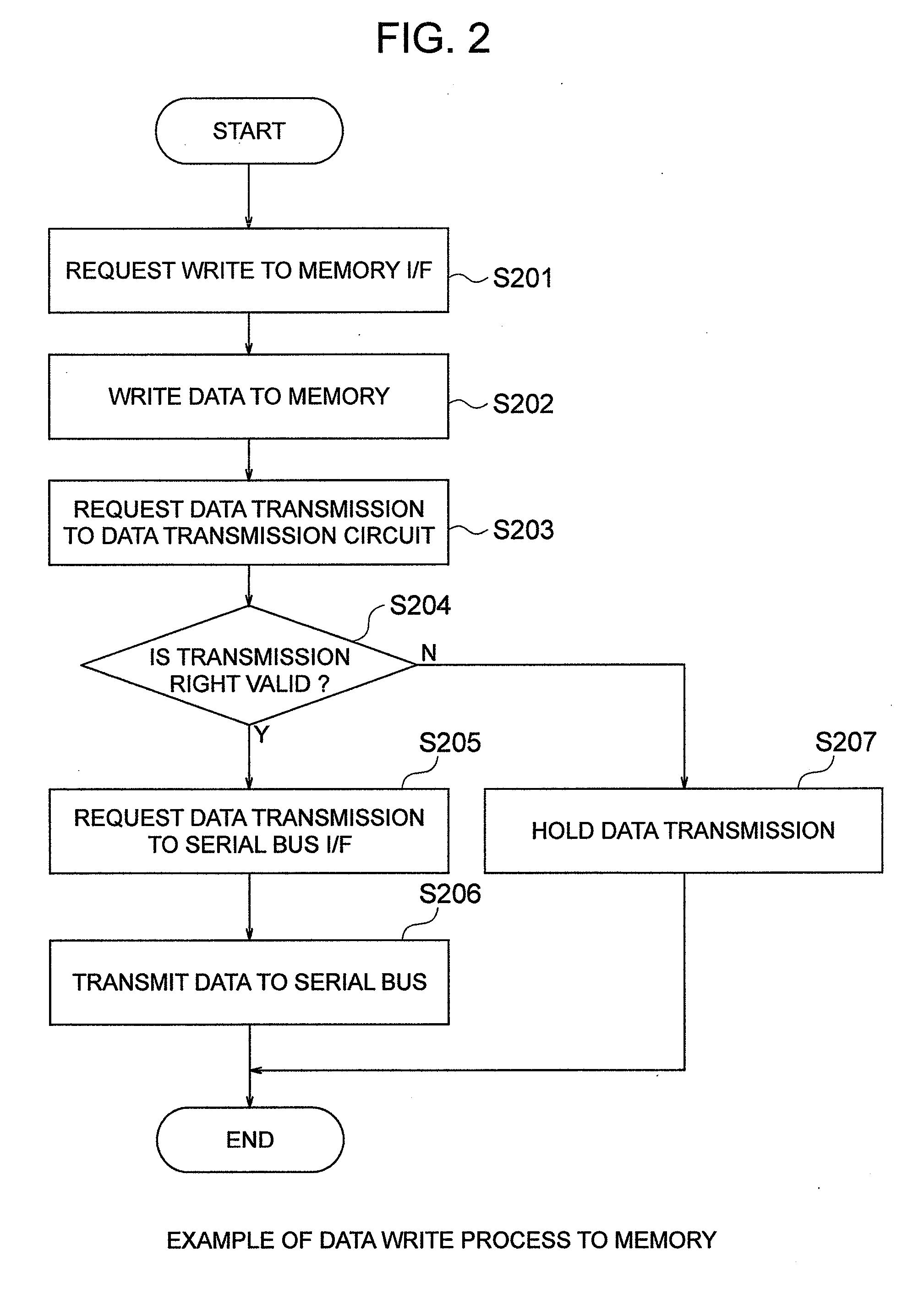
[0033]Also, by providing the processing device with a processor which is a processing unit and a memory which is a storage unit, by transmitting the write data to the memory to the serial bus when writing data from the processor to the memory, and by providing a unit to write to the memory within its own processing device when the transmission data from the other processing devices connected to the serial bus is received, it is possible to automatically make the memory contents of all the processing devices connected to the serial bus be consistent without the load of the processor. Further, as the serial bus is used only when the data is rewritten in this method, being different from the method to periodically transmit all the memory data to the serial bus like the method described in JP-A-2002-73584, even if the size of the shared memory is increased, it does not adversely affect the latency and the effective data communication speed.
[0034]In the present invention, if the data size which one processing device can change at a time is limited (for example, one data), the chance to change the data is equally given to each processing device connected to the serial bus. When a large amount of data is changed at one processing device, there is a case where the latency is increased because the wait has occurred, but the worst value of the latency which will be increased is predictable based on only the information regarding the process which that processing device intends to perform. Therefore, the worst latency in the case where it is limited to change only one data is easily predictable because it only depends on the number of the devices connected to the serial bus and it is adequate for the control use.
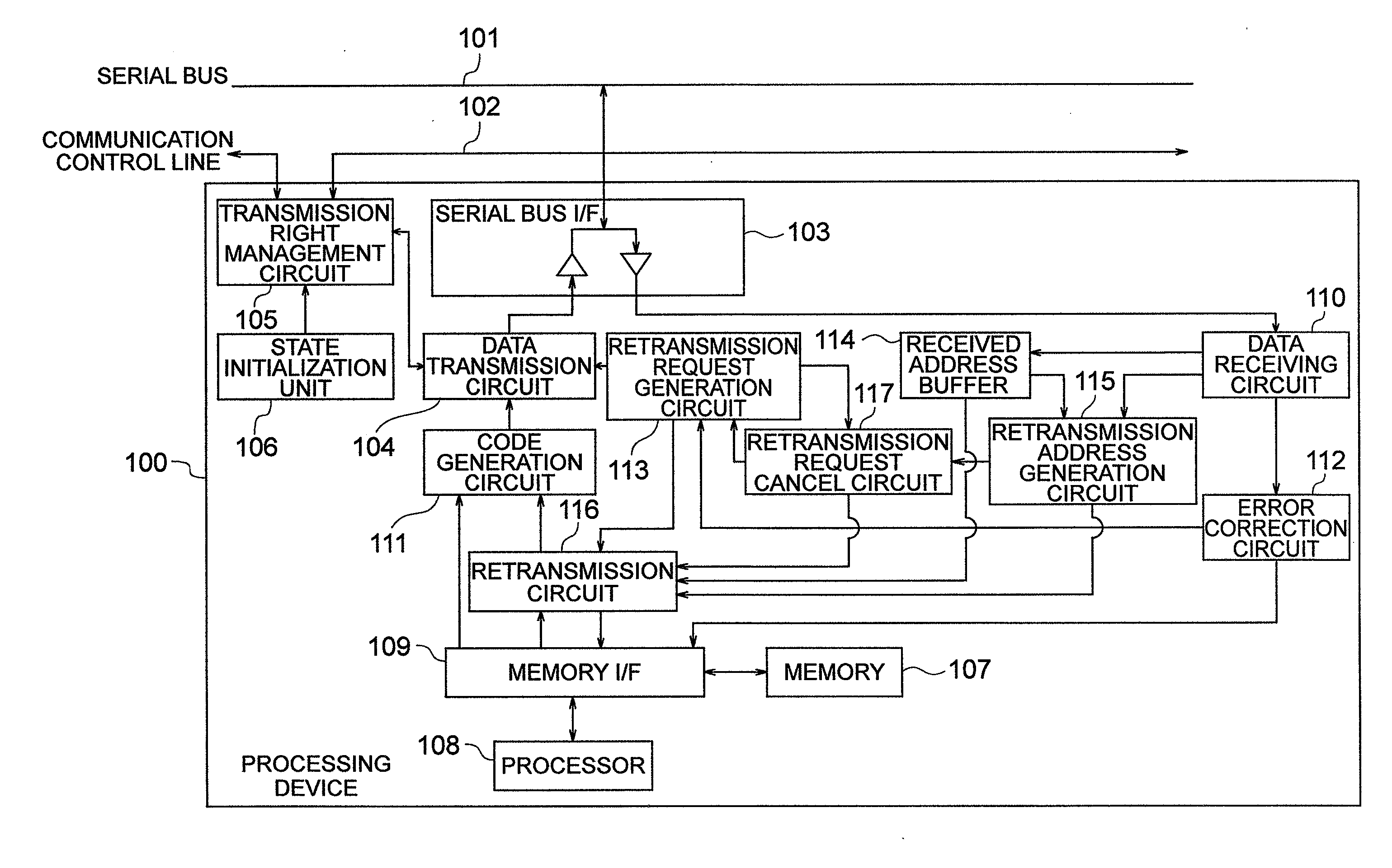
[0035]Also, according to the present invention, it is possible to realize the detection and correction of the communication error and the retransmission function by hardware. In the present invention, when the processing device which changed the data transmits the data to the serial bus, all the processing devices other than the processing device which transmitted receive the data simultaneously. The processing device which received the data individually performs the error detection / correction but when it detects an error which it cannot correct, transmits a retransmission request command when the transmission right comes around. On the other hand, as all the processing devices which could receive the data normally hold normal data, the processing device to which the transmission right comes around first after the retransmission request command was transmitted (it does not need to be the device which transmitted the changed data) can perform the retransmission. Also, even when the received data cannot be corrected, when the retransmission request of said data was sent out from the other processing device before the transmission right comes around to its own processing device, the retransmission is not requested in duplication for the same data and it waits for that the retransmission data is transmitted from the other processing device. Thereby the error detection / correction process and the retransmission process which conventionally become the load to the software all can be turned over to the hardware. Also, the error detection / correction process and the retransmission process are performed individually by the processing devices, but they are performed by all the processing devices connected to the serial bus in cooperation, the duplication of the retransmission process, etc. does not occur and the process can be performed promptly. Also, it becomes possible to precisely calculate the increased amount of the worst latency by the data retransmission.

Problems solved by technology

However, as the method makes the memory data of all the stations be consistent by periodically transmitting all the memory data shared between the plurality of stations on the serial bus, there is a problem that the delay time (latency) to reflect the data written in the memory of a certain station to the memory of other stations increases in proportion to the capacity of the memories which share the data.

Method used


Image

  • Data communications system and data communications method
  • Data communications system and data communications method
  • Data communications system and data communications method

Examples


Embodiment Construction

[0044]One embodiment of the present invention will be explained below referring to accompanying drawings.

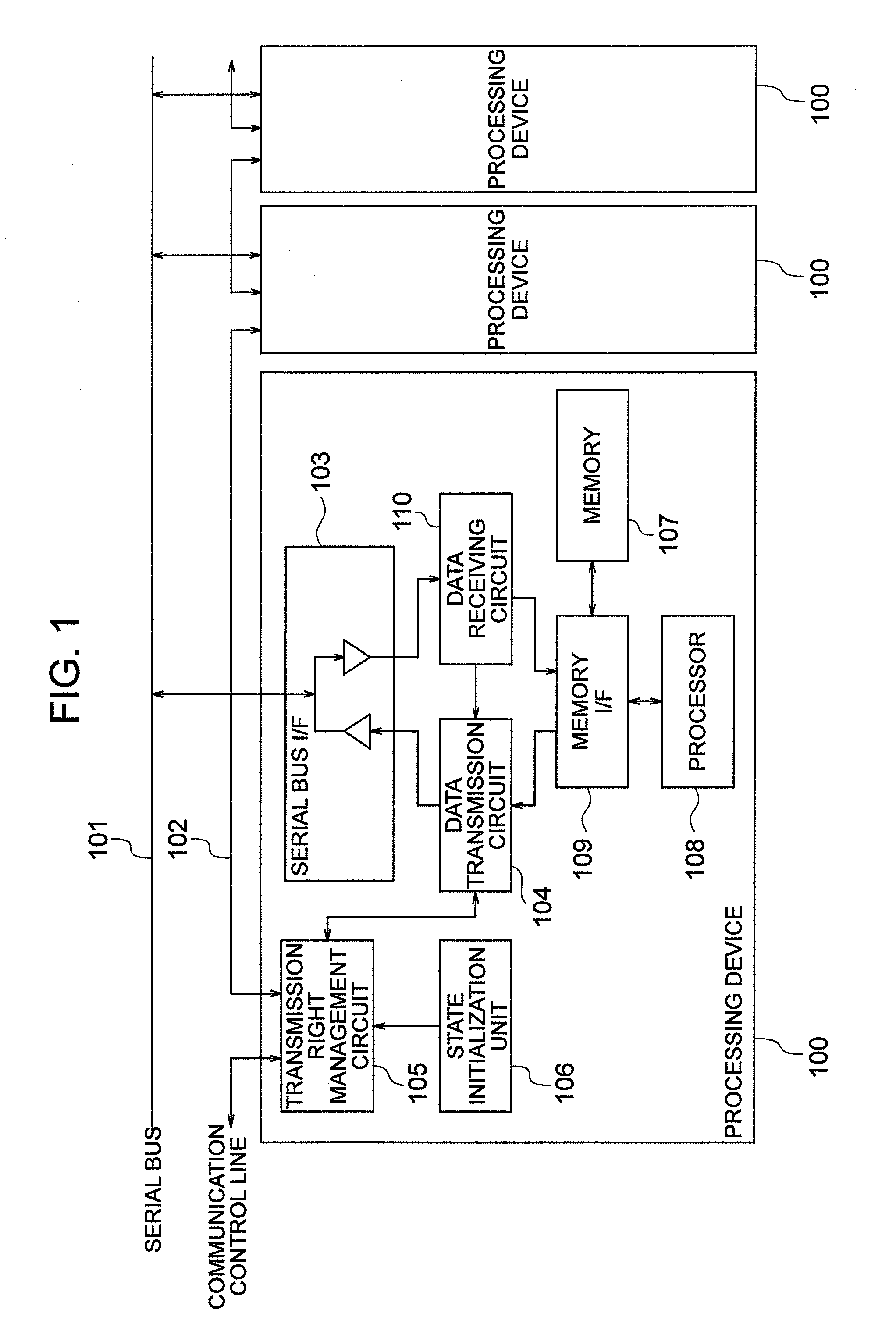
[0045]FIG. 1 shows an example of configuration of a data communications system of this embodiment. This embodiment is configured in that a plurality of processing devices 100 are connected to a serial bus 101 via a serial bus interface (I / F) 103, and between each processing device 100 it is sequentially chained, for example like a daisy chain, by communication control line 102 which performs the transfer of the data transmission right of the serial bus 101. Although the end part of the communication control line 102 is in the open state in FIG. 1, it is also possible to configure connecting the communication control line of the open part to each other and making it in the ring form.

[0046]Next, it will be explained about the configuration of the processing device 100 referring to FIG. 1. Here, as the processing devices connected to the serial bus 101 all have the same configuratio...


PUM


Abstract

A data communications system comprising a plurality of processing devices 100 connected to a serial bus 101 via a serial bus interface 103. The processing device 100 provides a communication control line 102 which connects each processing device in order and performs the transfer of transmission right of the serial bus is provided, a transmission right management unit 105 which is connected to the communication control line 102, performs the transfer of the transmission right and manages the state of the transmission right within its own processing device, a data transmission unit 104 which starts data transmission when the transmission right is valid and holds the data transmission when the transmission right is invalid, and a state initialization unit 106 which sets the initial state of the transmission right so that the transmission right of only one processing device is made to be valid at the initialization are included.

Description

BACKGROUND OF THE INVENTION[0001]The present invention relates to a data communications system and a data communications method to share memory data in real time between a plurality of distributed controllers connected by a serial bus.[0002]In built-in control equipment such as a robot, etc. on which multiple devices such as a sensor, an actuator, etc. are mounted and which needs complicated control using those devices, a configuration which performs cooperative control controlling those multiple devices by dividing them in some distributed controllers and having them communicate with each other is often adopted. There are some reasons why the configuration of distributed control type like this is adopted, but the reasons particularly important as built-in control are to make the equipment smaller by alleviating the concentration of wiring, to improve the noise problem with the shortening of the wiring distance, and to enhance the reliability. Also, in order to realize the configura...

Claims


Application Information

Patent Timeline
IPC IPC(8): H04L1/08G06F13/362G06F11/14
CPCH04L1/1829G06F13/37
Inventor IKE, KATSUHISA
Owner HITACHI LTD
Learn More