Method for the Decontamination of an Oxide Layer-containing Surface of a Component or a System of a Nuclear Facility

Inactive Publication Date: 2008-08-14
AREVA GMBH
View PDF11 Cites 5 Cited by
  • Summary
  • Abstract
  • Description
  • Claims
  • Application Information

AI Technical Summary

Benefits of technology

[0015]Before dissolution of the oxide layer present on a component surface is commenced after the oxidative treatment is complete, it is advantageous to rinse the oxide layer which has been treated in the way indicated above, for example with deionized water. However, in a preferred variant of the method, an oxide layer is, after the oxidative treatment, treated with steam, resulting in condensation of the steam occurring on the oxide layer. For steam to be able to condense, it may be necessary to cool the component surfaces or an oxide layer present thereon to a temperature below 100° C. It has surprisingly been found that as a result of this treatment, activity adhering in or on the oxide layers or component surfaces, for instance in particle form or in dissolved or colloidal form, goes over into the condensate and is removed from the surfaces together with this. This effect is clearly apparent at steam temperatures above 100° C. A further advantage of this procedure is the comparatively small amount of liquid condensate obtained.
[0016]Excess steam, i.e. steam which has not condensed on the treated surfaces, is removed from the system to be decontaminated or a container in which an oxidative treatment has been carried out and condensed. It is passed together with the condensate running off a component surface over a cation exchanger. In this way, the condensate is freed of activity and can be disposed of without problems. However, a further treatment carried out beforehand can be advantageous, especially when nitrate ions originating from the oxidative treatment of an oxide layer or acidification of a film of water by means of nitrogen oxides are present. The nitrates are preferably removed from the condensate by reacting them with a reducing agent, in particular hydrazine, to form gaseous nitrogen. A molar ratio of nitrate to hydrazine of from 1:0.5 to 2:5 is advantageously set here.

Problems solved by technology

In addition, the nitrogen oxide is less stable in aqueous solution than in the gas phase.

Method used


Image

  • Method for the Decontamination of an Oxide Layer-containing Surface of a Component or a System of a Nuclear Facility
  • Method for the Decontamination of an Oxide Layer-containing Surface of a Component or a System of a Nuclear Facility

Examples


Embodiment Construction

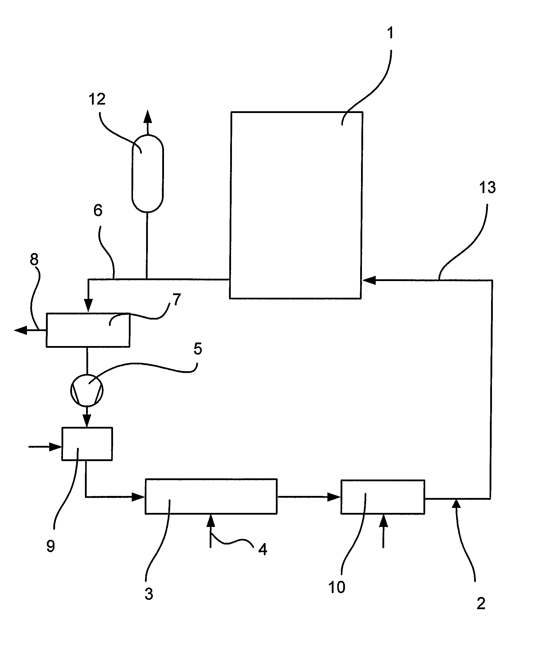
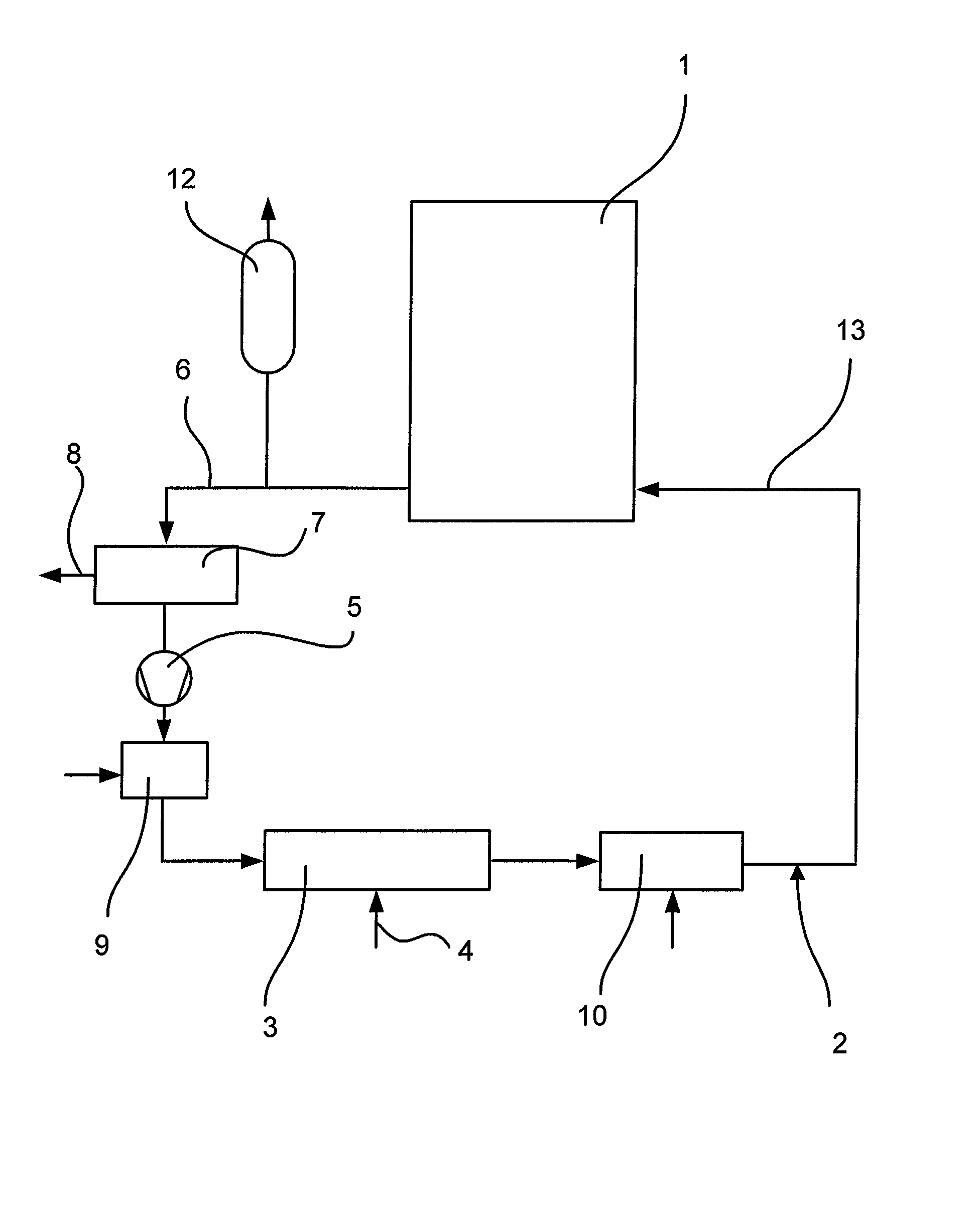
[0021]Referring now to the drawing FIGURE in detail, a system 1 to be decontaminated may, for example, be the primary circuit of a pressurized water reactor. First, the primary circuit is emptied. In the case of the decontamination of a component, for example a primary system pipe, the same is placed in a container. Such a container would correspond to the system 1 in the flow diagram. A decontamination circuit 2 is connected to the system 1 or the container. This circuit is gastight. Before startup, the decontamination circuit 2 and the system are tested for leaks, for example by evacuation. As a next step, the entire plant, i.e. system 1 and decontamination circuit 2, is heated. For this purpose, a feed station 3 for hot air and / or hot steam is arranged in the decontamination circuit 2. Air and / or steam are fed in via a feed line 4. The decontamination circuit 2 is also provided with a pump 5 in order to fill the system 1 with the appropriate gaseous medium and circulate the same,...


PUM

PropertyMeasurementUnit
Temperatureaaaaaaaaaa

Abstract

The invention relates to a method of decontaminating an oxide layer-comprising surface of a component or a system of a nuclear facility, wherein the oxide layer is treated with gaseous nitrogen oxide (NOx) as oxidizing agent.

Description

CROSS-REFERENCE TO RELATED APPLICATIONS[0001]This is a continuation, under 35 U.S.C. § 120, of copending international application PCT / EP2006 / 010927, filed Nov. 15, 2006, which designated the United States; this application also claims the priority, under 35 U.S.C. § 119, of German patent application DE 10 2005 056 727.4, filed Nov. 29, 2005; the prior applications are herewith incorporated by reference in their entirety.BACKGROUND OF THE INVENTIONField of the Invention[0002]The invention relates to a method of decontaminating an oxide layer-comprising surface of a component or a system of a nuclear facility. During operation of a light water reactor, an oxidation layer is formed on system and component surfaces and this has to be removed in order, for example, to keep the exposure of personnel to radiation as low as possible in the case of inspection work. A first choice as material for a system or a component is austenitic chromium-nickel steel, for example a steel containing 72% ...

Claims


Application Information

Patent Timeline
IPC IPC(8): B08B7/04B08B3/08B08B5/00
CPCG21F9/002G21F9/28G21F9/004
Inventor BERTHOLDT, HORST-OTTOMACIEL, TEREZINHA CLAUDETESTROHMER, FRANZ
Owner AREVA GMBH
Why Eureka
Try Eureka