Sealed thermal interface component

a technology of thermal interface and component, which is applied in the direction of electrical apparatus construction details, semiconductor/solid-state device details, lighting and heating apparatus, etc., can solve the problems of simple encapsulation of flowage materials, and achieve simple encapsulation of materials, excellent thermal transfer characteristics, and prevent the effect of encapsulation film ruptur

Active Publication Date: 2008-08-14
LUNDELL MFG CORP
View PDF52 Cites 12 Cited by
  • Summary
  • Abstract
  • Description
  • Claims
  • Application Information

AI Technical Summary

Benefits of technology

[0011]In preferred embodiments, in the encapsulation process, air is evacuated from the interior of the encapsulation, thus eliminating of minimizing air gaps or pockets from within the sealed thermal interface component. The encapsulating film is heat sealed around the foam-framed thermal pad portions. The minimal amount of air present in the evacuated component is conducive to excellent thermal transfer characteristics.
[0012]Compression of thermal interface management materials between heat source and heat-sinking components generally causes some flowing of the conformable material. This increase in pressure causes the thermal pads to expand along axes perpendicular to the axis of compression. Such compression and the resultant flowage can rupture a simple encapsulation of the material due to the buildup of internal pressure caused by the flowage. The foam frame prevents rupture of the encapsulating film by compressing and allowing lateral expansion by the thermal pads within the component. In embodiments not having the foam frame, selecting a thickness and geometry for the thermal pad that permits compression while limiting lateral expansion within a resilient film can prevent rupture of the encapsulating film. The presence of a bolt hole designed to facilitate attachment of the sealed thermal interface component can also provide additional room for lateral expansion of the thermal pad. The present invention thereby provides a thermal interface material flow management system.
[0013]Another feature and advantage of the preferred embodiments of the invention is the use of a heat-sealed encapsulating film. When heat-sealed, the encapsulating film prevents the exudation of silicone oils, maintains a vacuum within the sealed thermal interface component, enhancing thermal conductivity, and accommodates volumetric displacement of the foam-framed or non-framed thermal pad without rupture or leakage during compression.
[0014]A further feature and advantage of preferred embodiments of this invention is presented relating to the optional use of foam as a framing component within the sealed thermal interface component. Components formed from a simple encapsulation of conformable heat transfer materials may not adequately contain fluids that may exude from the material, particularly when the component is severely compressed. The foam frame is available for absorbing the silicone oil exuded from the thermal management material in the component. In other applications, the film-encapsulated thermal pad may adequately contain fluids that may exude from the material, even when compressed, and the thermal interface component need not include the foam frame. The present invention thereby provides a thermal interface material fluid exudation management system through absorption and containment.
[0015]Another feature and advantage of the preferred embodiments of this invention is the creation of a vacuum within the encapsulating film while simultaneously heat sealing the encapsulating film. This removes and maintains the absence of air spaces from the sealed thermal interface. Air may inhibit heat transfer and the vacuum-induced lack of air within the thermal interface component increases the thermal transfer performance.
[0016]Another feature and advantage of the preferred embodiments of the invention is the presence of a control means for silicone oil in the thermal interface. Said means comprises a containment for the oil as well as an liquid-absorbing capability within the thermal interface.

Problems solved by technology

Such compression and the resultant flowage can rupture a simple encapsulation of the material due to the buildup of internal pressure caused by the flowage.

Method used


Image

  • Sealed thermal interface component
  • Sealed thermal interface component
  • Sealed thermal interface component

Examples


Embodiment Construction

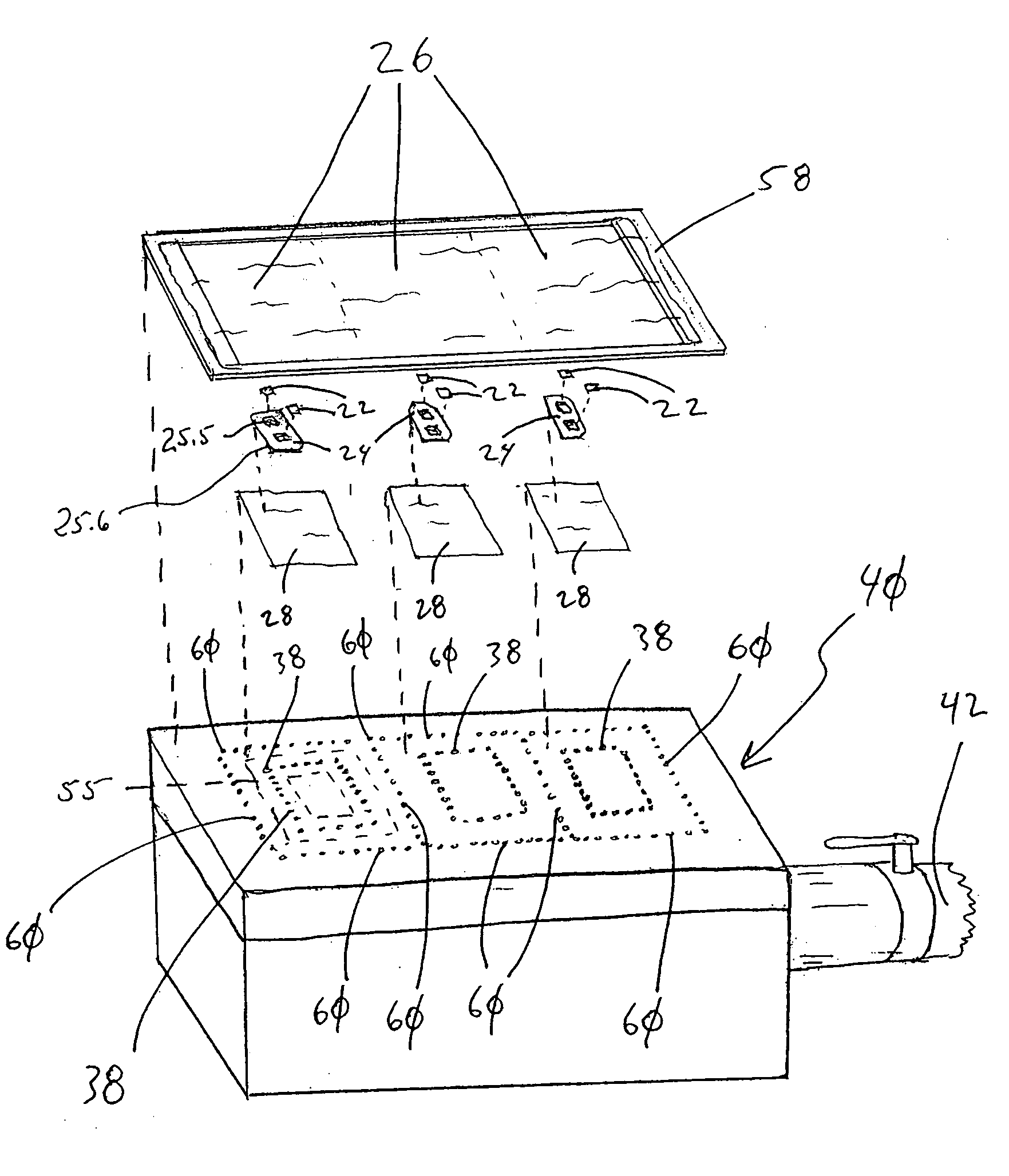
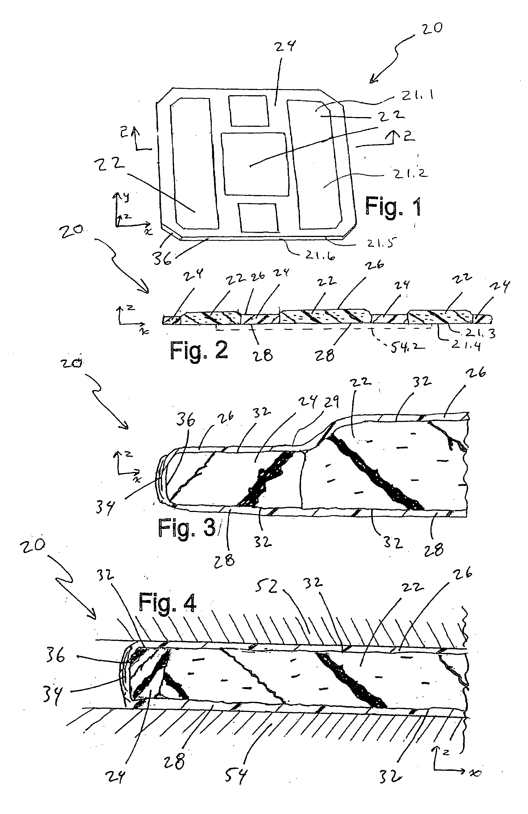
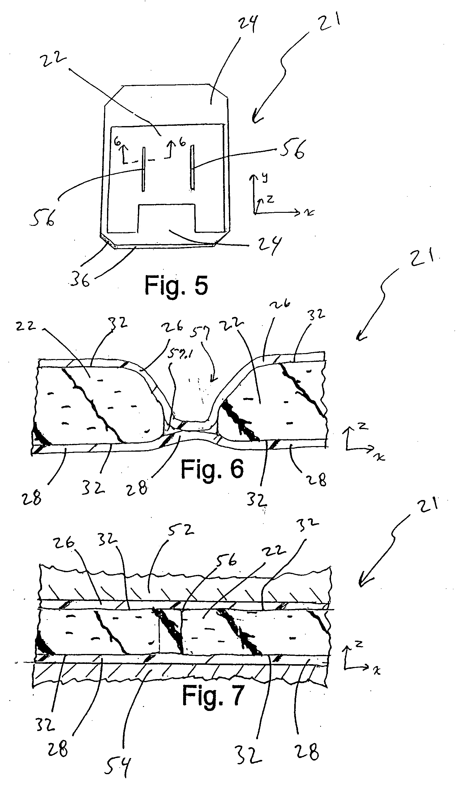
[0035]The present invention includes a heat-sealed thermal interface component for facilitating heat transfer between a heat source and a heat-sinking component. Referring to FIGS. 1, 2, 5, 6, and 13-16, different embodiments of the sealed thermal interface component 18, 19, 20, 21 are illustrated. The components generally have a top side 21.1 with a top surface 21.2, a bottom side 21.3 with a bottom surface 21.4, and a side 21.5 with a side surface 21.6. In preferred embodiments the component is a sheet configuration with a maximum thickness of about 0.03 inches to about 0.50 inches (in the z direction of the x-y-z coordinate system) and surface area (in the x and y plane) of about 2 square inches to about 36 square inches. More preferably, the component has a thickness of 0.06 to 0.16 inches. The component may have a thickness that varies slightly due to different thicknesses of the base components and compression that occurs during manufacture, specifically the partial evacuation...


PUM

PropertyMeasurementUnit
thicknessaaaaaaaaaa
surface areaaaaaaaaaaa
thicknessaaaaaaaaaa

Abstract

A sealed thermal interface component minimizes or eliminates the exudation of fluids, such as silicone oils, while preserving the excellent thermal conductivity of silicon-based thermal pad materials and enhancing the conformability of the component. In an example embodiment, one or more thermal pads are formed of conformable thermal management material that may exude fluid under elevated temperatures or over time. Film encapsulates the thermal pad or pads, forming a sealed and partially evacuated thermal interface component. In one embodiment of the invention, the thermal pad or pads are formed of an elastomeric silicon-based thermally conductive material and the film is made of polyurethane.

Description

RELATED APPLICATIONS[0001]This application is a continuation-in-part of application Ser. No. 11 / 704,005 filed Feb. 8, 2007, which is hereby fully incorporated herein by reference.BACKGROUND OF THE INVENTION[0002]This invention relates to thermal management materials that conduct heat from a heat source to a heat-sinking component and, more particularly, components that interface between a heat source and a heat switch.[0003]During operation, IC devices produce heat. Efficient cooling systems are sometimes necessary to prevent the failure of IC devices due to this heat. Certain types of cooling systems work by transferring heat from the surface of a heat source to a heat-sinking component that dissipates the heat. Heat sinking components typically are metal, for example aluminum, and have expanded surface areas to transfer heat to the environment or may have other mechanical cooling means. When the surface of a heat source, such as an integrated circuit or a module or package contain...

Claims


Application Information

Patent Timeline
Patent Type & Authority Applications(United States)
IPC IPC(8): F28F7/00
CPCF28F13/00H01L23/433F28F2013/005H01L2924/0002H01L2924/00
Inventor LUNDELL, TIMOTHY J.LUNDELL, THOMAS L.
Owner LUNDELL MFG CORP
Why Eureka
Try Eureka