
Cable for Stringed Musical Instruments

Inactive Publication Date: 2008-08-14
WL GORE & ASSOC INC
View PDF8 Cites 15 Cited by
  • Summary
  • Abstract
  • Description
  • Claims
  • Application Information

AI Technical Summary

Benefits of technology

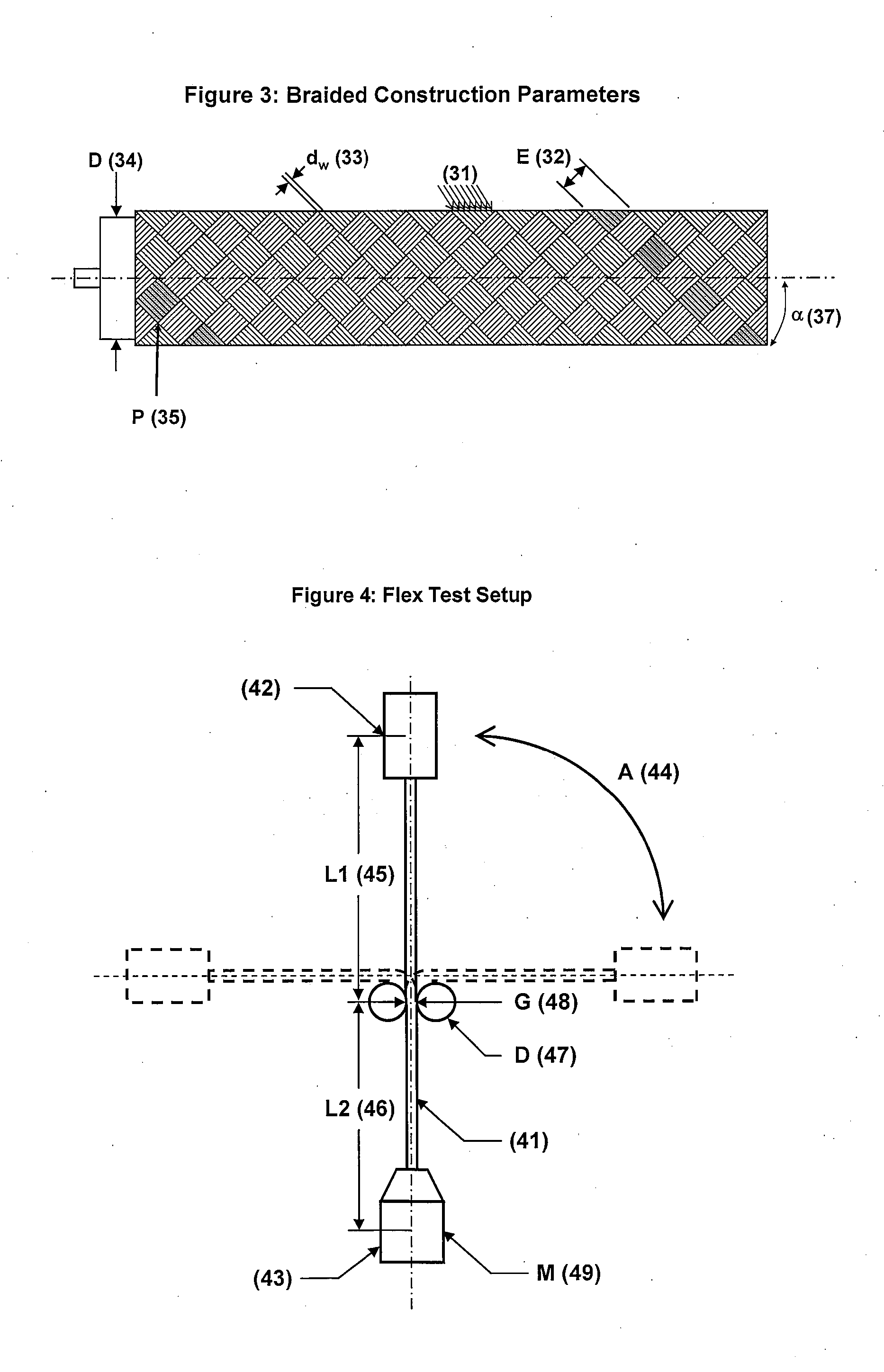
[0020]dw=geometrical diameter of shield component wire
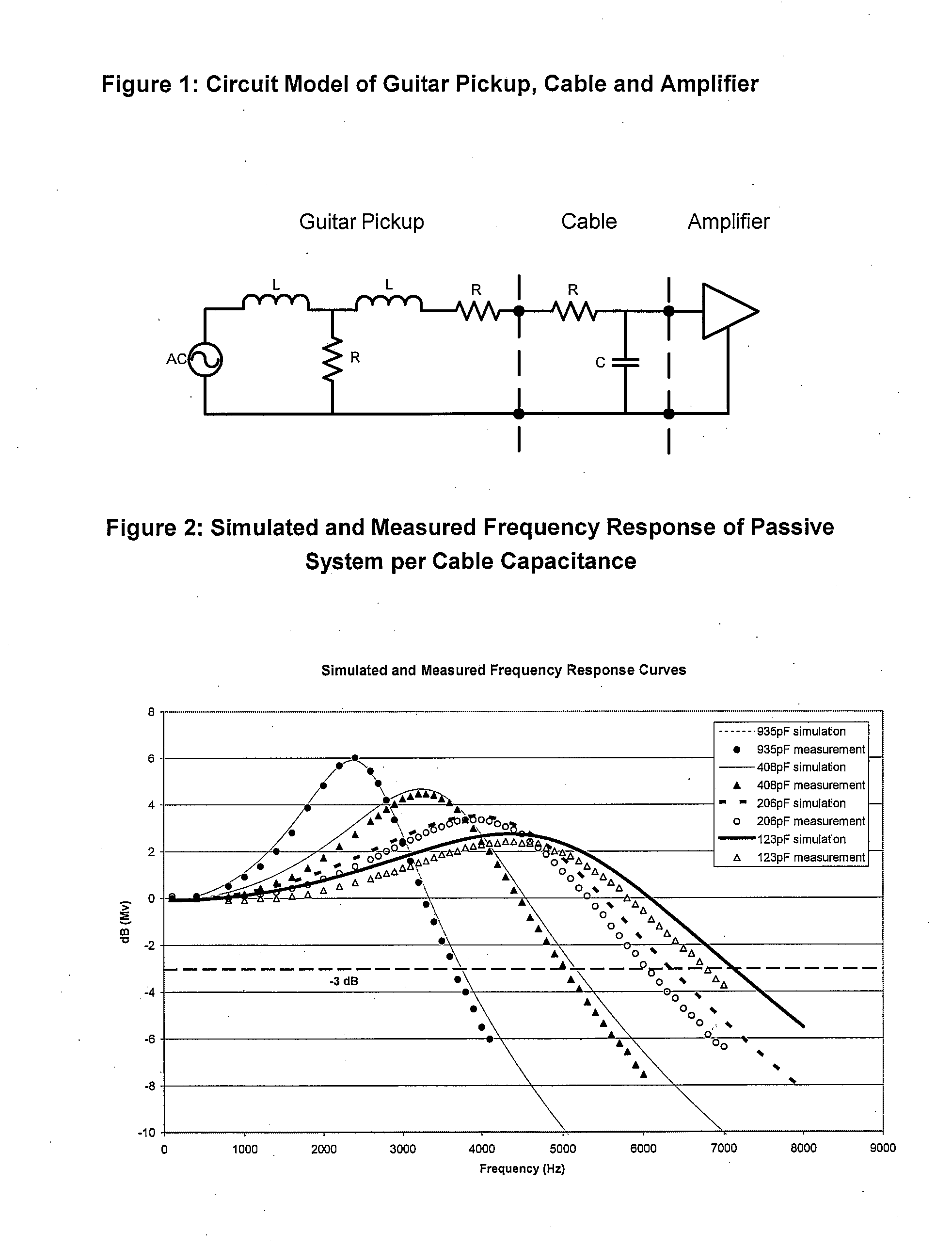
[0024]While there are several ways to reduce cable capacitance, each has a distinct disadvantage:
[0025]Reducing the relative dielectric constant of the material between the center conductor and shield: Several inexpensive materials, such as polyethylene, can have gas injected into them during processing to reduce the dielectric constant to approximately 1.5. To achieve dielectric constants below this requires more expensive processes and lower dielectric materials such as fluoropolymers.
[0026]Increasing the effective inner diameter of the outer shield: This option is bounded by the cost of adding material and the practical limits of the cable diameter that will fit into connector sizes.
[0027]Reducing the effective outer diameter of the center conductor: Typical commercially available cables use 18-22 AWG

Problems solved by technology

While there are several ways to reduce cable capacitance, each has a distinct disadvantage:
To achieve dielectric constants below this requires more expensive processes and lower dielectric materials such as fluoropolymers.
This compromises both flex life and tensile strength of the cable.

Method used


Image

  • Cable for Stringed Musical Instruments
  • Cable for Stringed Musical Instruments
  • Cable for Stringed Musical Instruments

Examples


Embodiment Construction

I. Description of the Preferred Embodiments

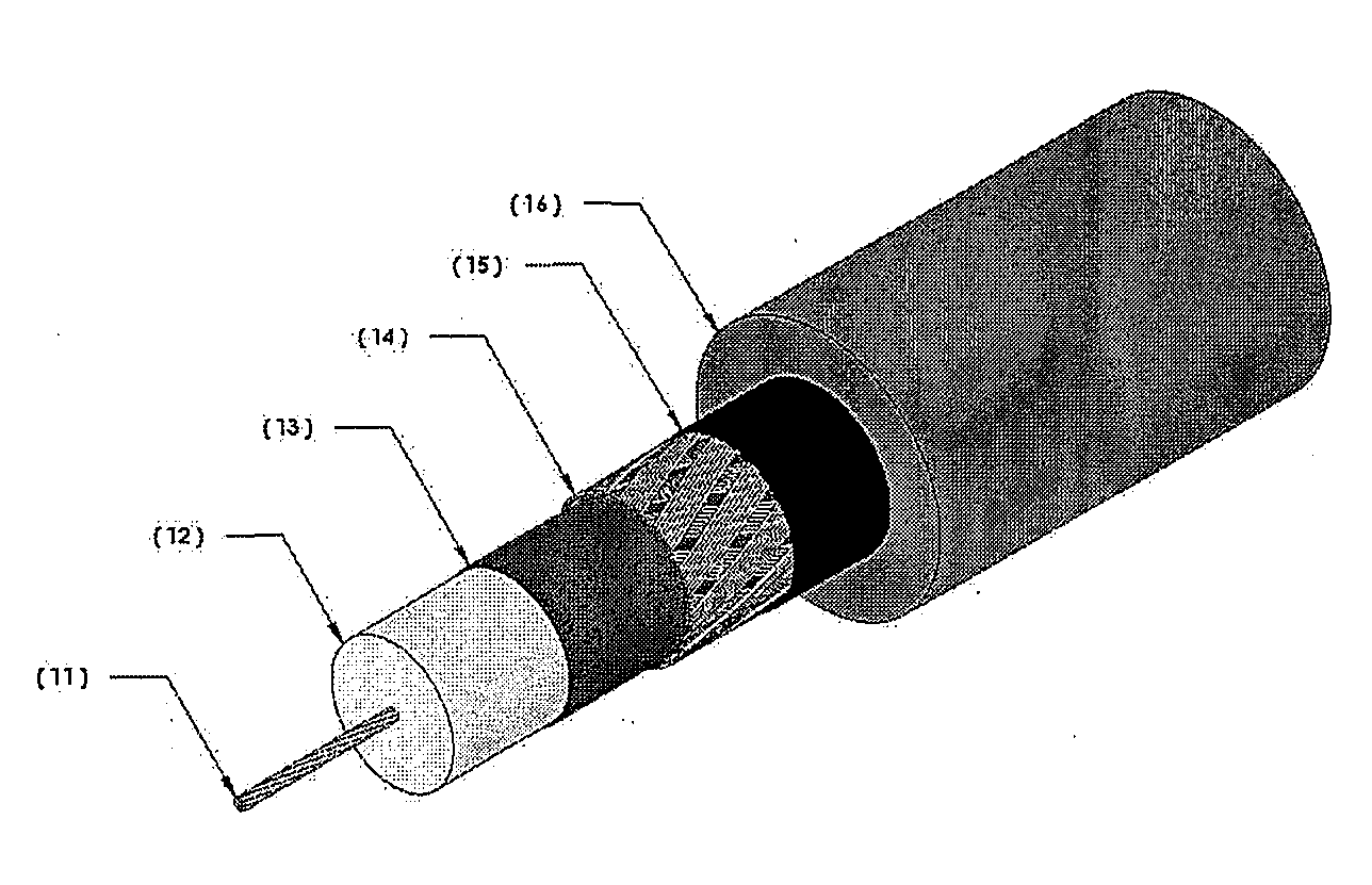
[0039]The present invention will now be described in connection with the preferred embodiment illustrated in FIG. 7. As shown in FIG. 7, the inventive instrument cable comprises a center conductor 11, dielectric 12, semi-conductive layer 13, shield 14, optional binder 15, and jacket 16.

[0040]Dielectric 12 around center conductor 11 is preferably foamed polyethylene. As discussed above, minimizing the effective outer diameter of center conductor 11 reduces capacitance. Although it might alternatively be possible to use a larger center conductor 11 and reduce capacitance by increasing the effective inner diameter of the shield 14, such a solution is not practical with an instrument cable which has specific requirements for the ultimate cable outer diameter (preferably less than 0.375 inches). Accordingly, applicants have discovered that in conjunction with reducing the effective outer diameter of center conductor 11, it is necessary to ensure...


PUM


Abstract

A center conductor having an effective outer diameter; a dielectric material around the center conductor, a semi-conductive layer around the dielectric material, an outer conductor, or shield, around the dielectric material; the shield having an effective inner diameter; wherein the center conductor has a cross-sectional area of 3.141×10⁻⁴ in2 or less; wherein the cable has a capacitance of about 15 pF / ft or less; wherein the cable maintains electrical continuity under a tensile force of 25 lbf or greater; wherein the cable has a flex life of greater than about 30,000 cycles; and wherein the cable is a musical instrument cable.

Description

CROSS REFERENCE TO RELATED APPLICATION[0001]This application claims the benefit of commonly owned and co-pending U.S. Provisional Application No. 60 / 889,347 filed on Feb. 12, 2007.FIELD OF THE INVENTION[0002]This invention relates to an improved cable for stringed musical instruments, and more particularly, to an improved cable for stringed musical instruments with low capacitance.BACKGROUND OF THE INVENTION[0003]Guitars and other stringed instruments are often amplified by attaching a passive magnetic pickup in close proximity to the vibrating metallic strings and connecting this pickup to an amplifier and speaker using a cable. The vibrating string changes the magnetic flux within the core of the pickup. This flux change induces a voltage change in the outer coils of the pickup, thus completing the translation of mechanical vibration to electrical signal. This signal is transmitted through the cable to the amplifier.[0004]The cable connecting the pickup to the amplifier is typical...

Claims


Application Information

Patent Timeline
IPC IPC(8): H01B9/02
CPCG10H2240/171H01B11/1895H01B11/1878H01B11/1839
Inventor ALLEN, JOHN C.NEITZEL, EDWARDTHEORIN, CRAIG
Owner WL GORE & ASSOC INC
Learn More