Vehicle Drive System And Electronic Circuit Device Used For The Same

a technology of electronic circuit device and drive system, which is applied in the direction of electric devices, motor/generator/converter stoppers, process and machine control, etc., can solve the problems of increasing becoming difficult to extricate the vehicle from the rollback condition, etc., to reduce the acceleration of the reverse drive, improve the vehicle running performance, and reduce the speed of the reverse driv

Inactive Publication Date: 2008-08-14
HITACHI LTD
View PDF11 Cites 47 Cited by
  • Summary
  • Abstract
  • Description
  • Claims
  • Application Information

AI Technical Summary

Benefits of technology

[0007]Recent years have seen an increase in the number of motor-driven vehicles typified by electric vehicles and hybrid electric vehicles. These automobiles, being capable of reducing or zeroing emissions, are sensitive to the global environment and can make use of the motor driving force in various aspects during vehicle movement utilizing the motor response, thereby improving the vehicle running performance. Like techniques disclosed for example in JP-A-2002-58101, JP-A-2006-311644, and JP-A-2006-101642, the use of the motor driving force for restraining rollback of the vehicle makes it possible to improve the running performance when the vehicle is started on an upgrade.
[0008]In order to further generalize motor-driven vehicles continuously, it is necessary to further improve the commodity value of motor-driven vehicles. In order to accomplish this subject, it is necessary to further improve the vehicle running performance in various aspects during vehicle movement, for example, by making use of the motor driving force more effectively in various aspects during vehicle movement as well as optimally controlling the motor drive in various aspects during vehicle movement.

Problems solved by technology

For example, when the vehicle is started on a steep grade, if the vehicle acceleratively rolls back until the brake is released and then the accelerator pedal is depressed and accordingly the rollback speed increases too much, it becomes difficult to extricate the vehicle from the rollback condition.

Method used


Image

  • Vehicle Drive System And Electronic Circuit Device Used For The Same
  • Vehicle Drive System And Electronic Circuit Device Used For The Same
  • Vehicle Drive System And Electronic Circuit Device Used For The Same

Examples


first embodiment

[0037]A first embodiment will be explained below with reference to FIGS. 1 to 14.

[0038]The present embodiment is an example where an electric drive system according to the present invention is adopted to a four-wheel drive hybrid electric vehicle not having a motor drive battery.

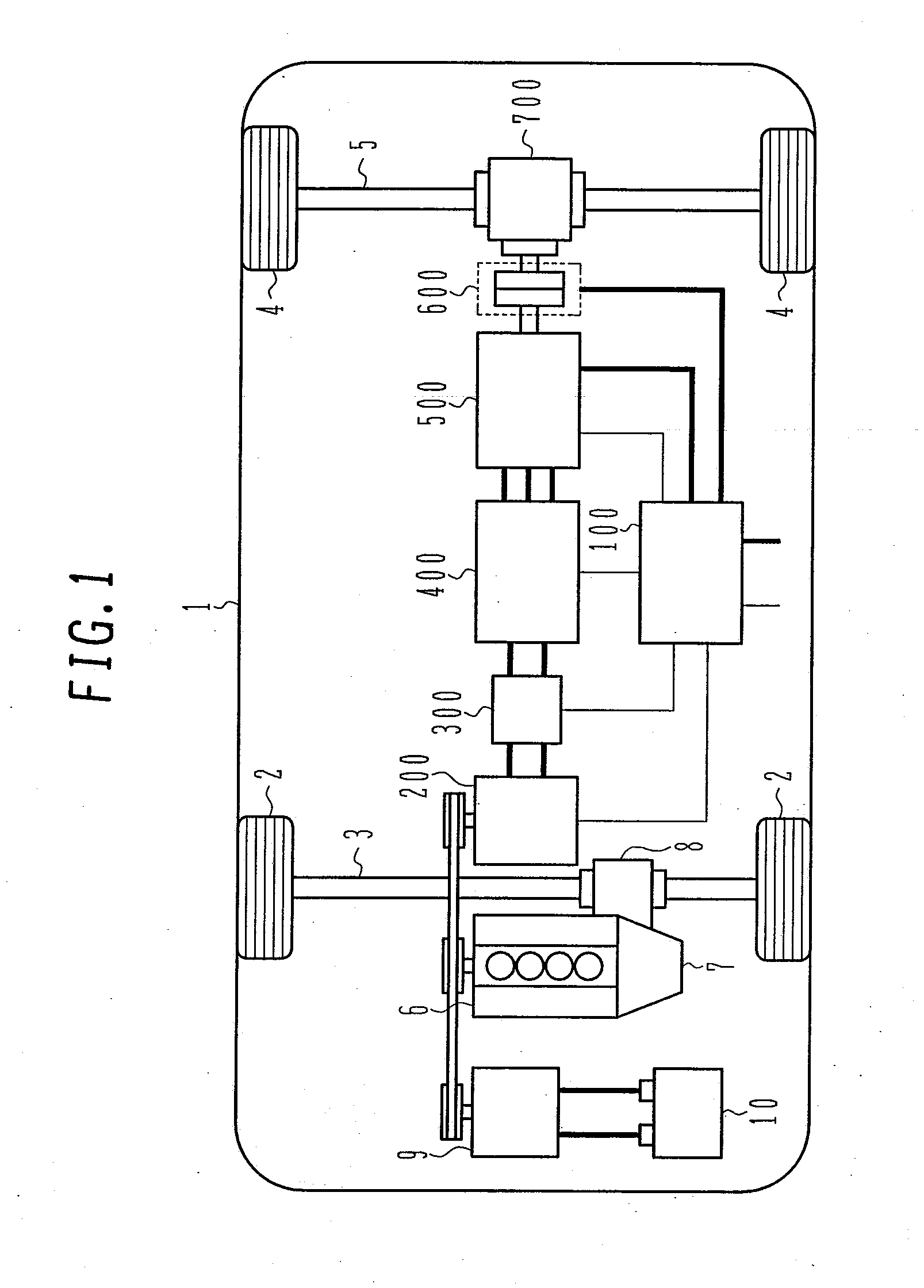
[0039]First, a configuration of the drive system of the four-wheel drive hybrid electric vehicle not having a motor drive battery will be explained below with reference to FIG. 1.

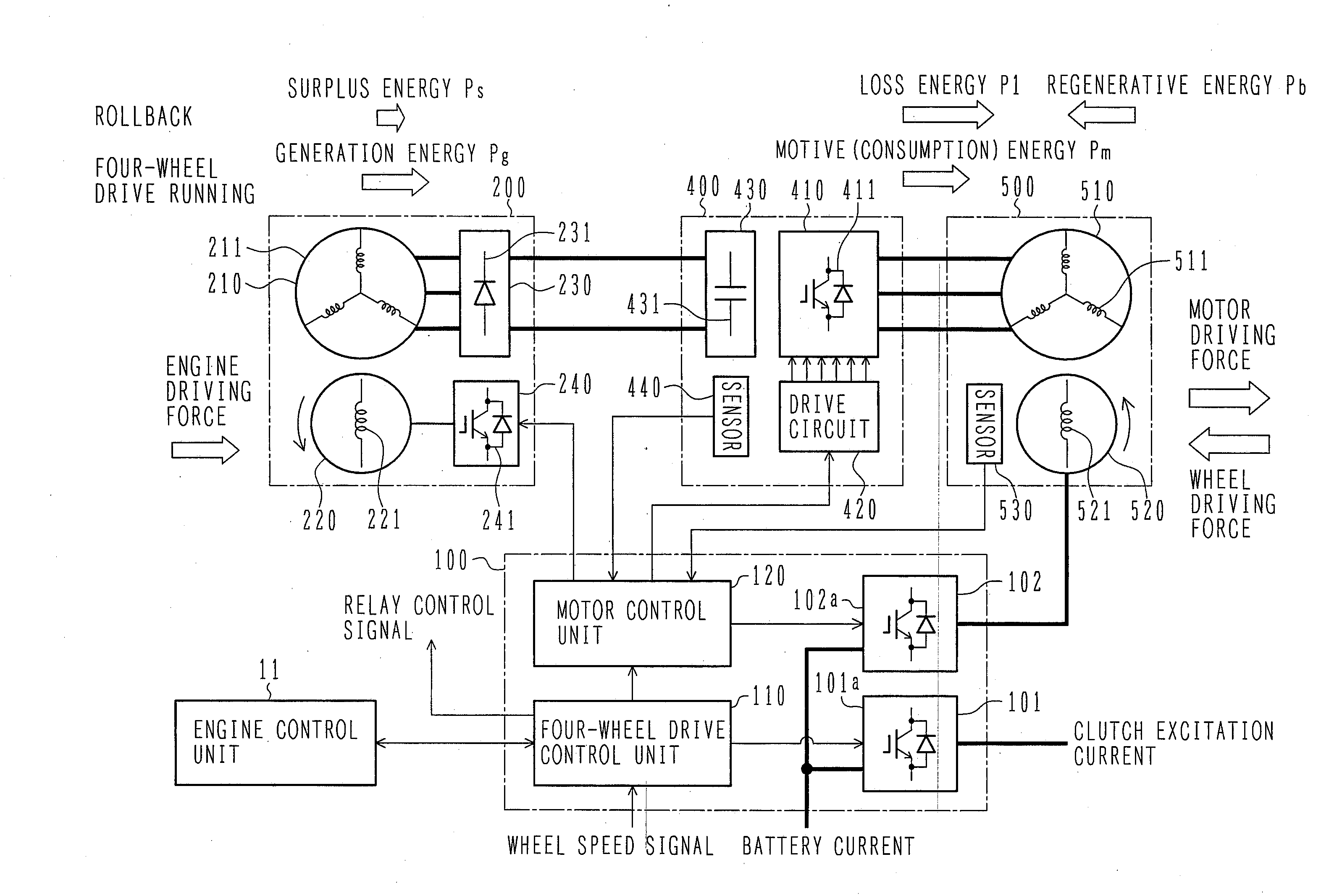
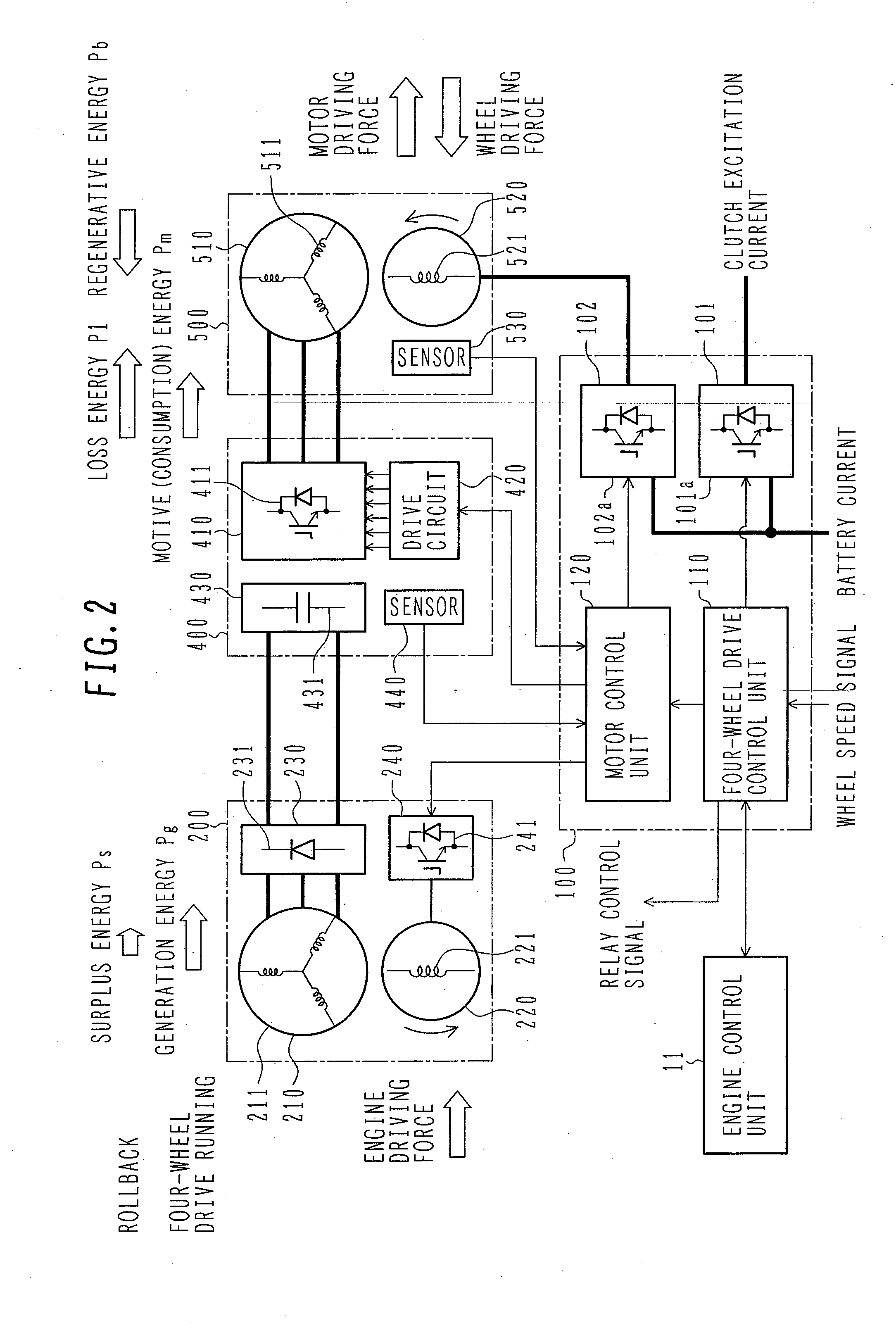
[0040]In FIG. 1, control cables for transmitting control signals are drawn with thin solid lines, and electric cables for supplying electric energy are drawn with solid lines thicker than those of control cables. This applies also to FIG. 2 to be mentioned later.

[0041]A four-wheel drive hybrid electric vehicle not having a motor drive battery (hereinafter referred to as four-wheel drive vehicle 1) is a hybrid drive vehicle having one drive system driven by an engine 6 and the other drive system driven by a motor 500 such that front ...

second embodiment

[0251]A second embodiment of the present invention will be explained blow with reference to FIG. 15.

[0252]The present embodiment is an improvement over the first embodiment. The present embodiment is characterized in that a temperature compensation unit 190 for performing compensation for the inverter controller 160 according to the temperature of the armature winding 511 of the motor 500 is provided in the rollback controller 150.

[0253]Other configurations are the same as those of the first embodiment and therefore not explained.

[0254]In accordance with the present embodiment, the regenerative energy that the motor 500 will generated based on rollback is consumed by making the loss energy (P1=3×Armature current Ima2×Armature winding resistance R) of the motor 500 larger than that at the time of normal four-wheel drive control, like in the first embodiment. As shown in the formula, the magnitude of the loss of the motor 500 is proportional to the resistance of the armature winding 5...

third embodiment

[0261]A third embodiment of the present invention will be explained below with reference to FIG. 16.

[0262]The present embodiment is an improvement over the first embodiment. The present embodiment is characterized in that a rollback current calculator 191 for calculating the current command value for rollback is provided in the rollback controller 150 so that surplus power supplied from the drive generator 200 coincides with the surplus power command value obtained through calculation for rollback.

[0263]Other configurations are the same as those of the first embodiment and therefore not explained.

[0264]With the temperature compensation method of the second embodiment, it is necessary to constantly obtain the rollback base loss in response to change of the operating point (torque, rotational speed) of the motor 500 and, further, command values are used for all calculations. Therefore, if a difference arises between the command value and the actual value, the regenerative energy may e...


PUM


Abstract

An object of the present invention is to further improve the running performance of the vehicle. This object can be solved by providing a rollback controller 150 used for controlling the operation of an inverter 400 to control an armature current of the motor 500 in a motor control equipment 120 so that, when a rollback is detected and a rollback speed exceeds a rollback speed limit, the rollback is maintained and the rollback speed is limited by the driving force of the motor 500, with the rollback speed limit value as a target speed recognized.

Description

BACKGROUND OF THE INVENTION[0001]1. Field of the Invention[0002]The present invention relates to a vehicle drive system and an electronic circuit device used for the same, and typically to a technique for improving the running performance of a vehicle.[0003]2. Description of the Related Art[0004]Examples of the related art of improving the running performance of a vehicle include techniques disclosed, for example, in JP-A-2002-58101, JP-A-2006-311644, and JP-A-2006-101642.[0005]JP-A-2002-58101 discloses a motor control technique which sets a motor torque command value to a positive value when the rotational speed of a motor is zero, and gradually increases the motor torque command value in the positive direction as the rotational speed increases in the negative direction. Further, JP-A-2006-311644 discloses a vehicle drive technique for making the motor driving force in the vehicle traveling direction when a rollback is detected larger than that otherwise. It is assumed that these d...

Claims


Application Information

Patent Timeline
Patent Type & Authority Applications(United States)
IPC IPC(8): B60K31/00H02P25/30B60L50/16
CPCB60K6/442Y02T10/7275B60L15/2009B60L2240/423B60L2240/425B60L2240/461B60L2240/465B60L2240/486B60W10/06B60W10/08B60W20/00B60W30/18118B60W2510/0604B60W2510/087B60W2520/10B60W2520/28B60W2540/04B60W2540/10B60W2540/12B60W2540/16B60W2710/083B60W2720/28Y02T10/6234Y02T10/6265Y02T10/6286Y02T10/642B60L3/0061B60L3/04B60L7/14B60L7/18B60L11/123B60L11/14B60L11/1868B60L2210/40B60L2220/14B60L2240/36B60L2240/421B60L2240/427B60L2240/429B60L2250/24B60L2250/26B60L2260/28B60L15/2081B60K6/52B60L50/61B60L50/16B60L58/20B60W2540/215Y02T10/62Y02T10/64Y02T10/70Y02T10/72Y02T10/7072B60W50/082B60W50/085B60W2510/102
Inventor KANEKO, SATORUYAMAMOTO, TATSUYUKISUWA, TOKIHITOIMURA, SHINYA
Owner HITACHI LTD
Why Eureka
Try Eureka