
Phosphor, Method For Producing Same, And Light-Emitting Device Using Same

Inactive Publication Date: 2008-08-14
SUMITOMO ELECTRIC IND LTD
View PDF4 Cites 25 Cited by
  • Summary
  • Abstract
  • Description
  • Claims
  • Application Information

AI Technical Summary

Benefits of technology

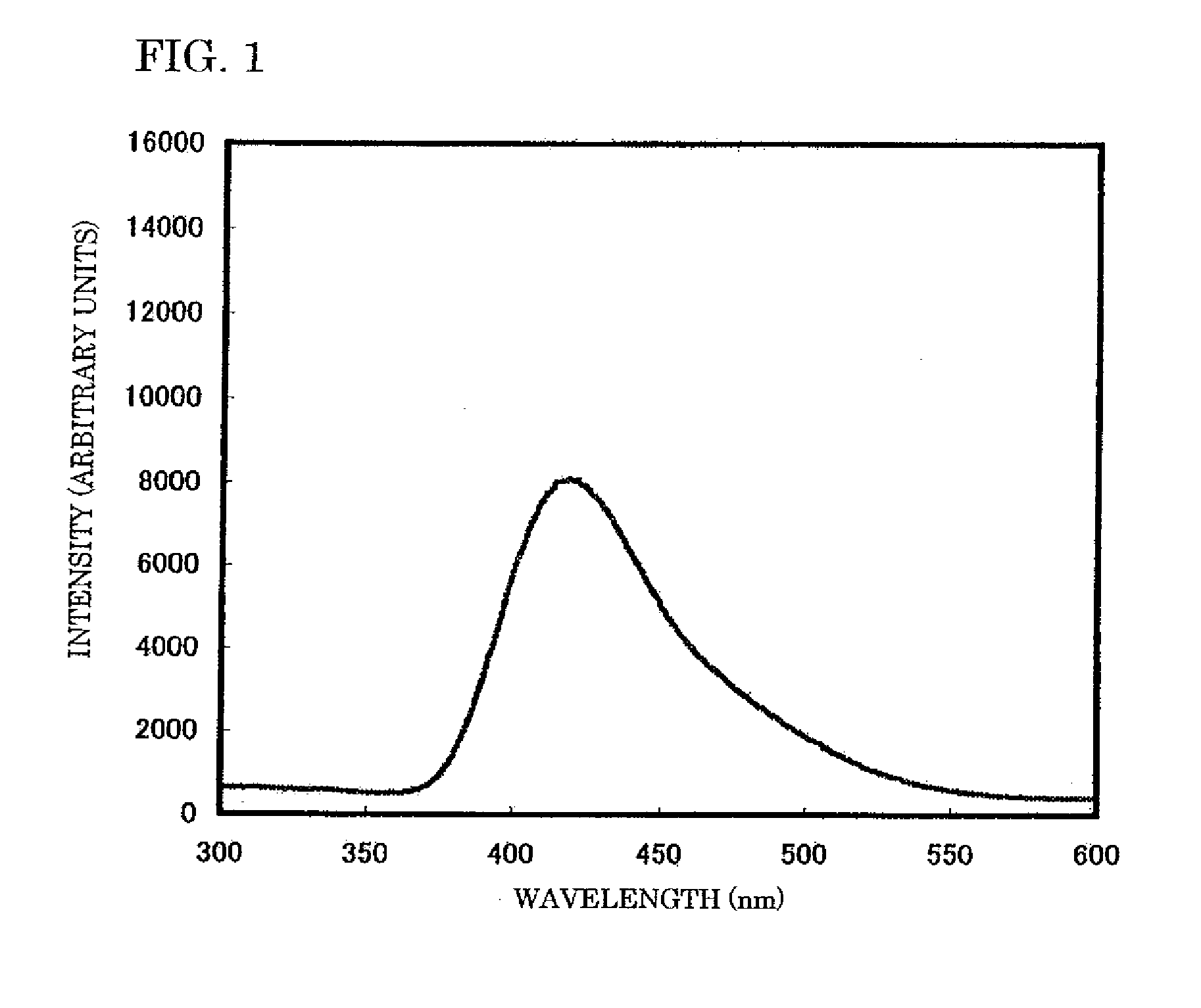
[0014]Therefore, in order to solve the problems described above, an object of the present invention is to provide a phosphor that produces B-Cu emissions and to provide a method for manufacturing the phosphor when an activator comprising Ag or Cu is used in a ZnS-based phosphor. Another object of the present invention is to provide a phosphor in which EL UV emissions having a short wavelength occur when Cu is used as an activator, and to provide a method for manufacturing the phosphor. Yet another object of the present invention is to provide a phosphor that generates B-Cu emissions having not only G-Cu bluish purple emissions, but also an emission peak in the UV region on the short wavelength side of the G-Cu bluish purple emissions. This object is achieved by crystallizing ZnS together with another sulfide, finely adjusting the amount of Ag or other activators and co-activators, and finely adjusting the method for mixing the starting materials, the baking conditions, and making other adjustments, so that Ag entry into the interstices is facilitated when Ag is used as an activator. Another object of the present invention is to provide a phosphor in which interstitial doping of Ag ions can be stabilized to allow short-wavelength light to be emitted when an activator comprising Ag is used, and in which an electroconductive phase required for EL emissions can be formed along crystal grain boundaries, twin boundaries, and dislocations.
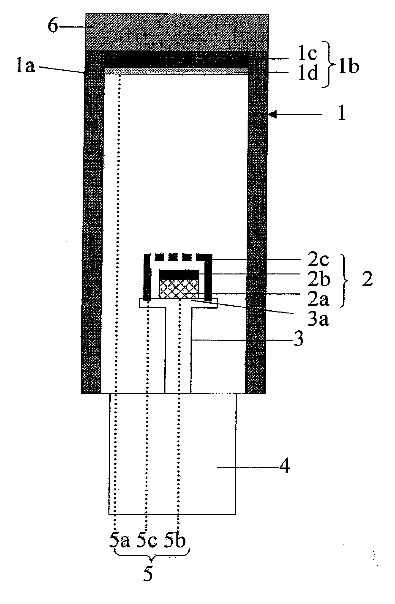
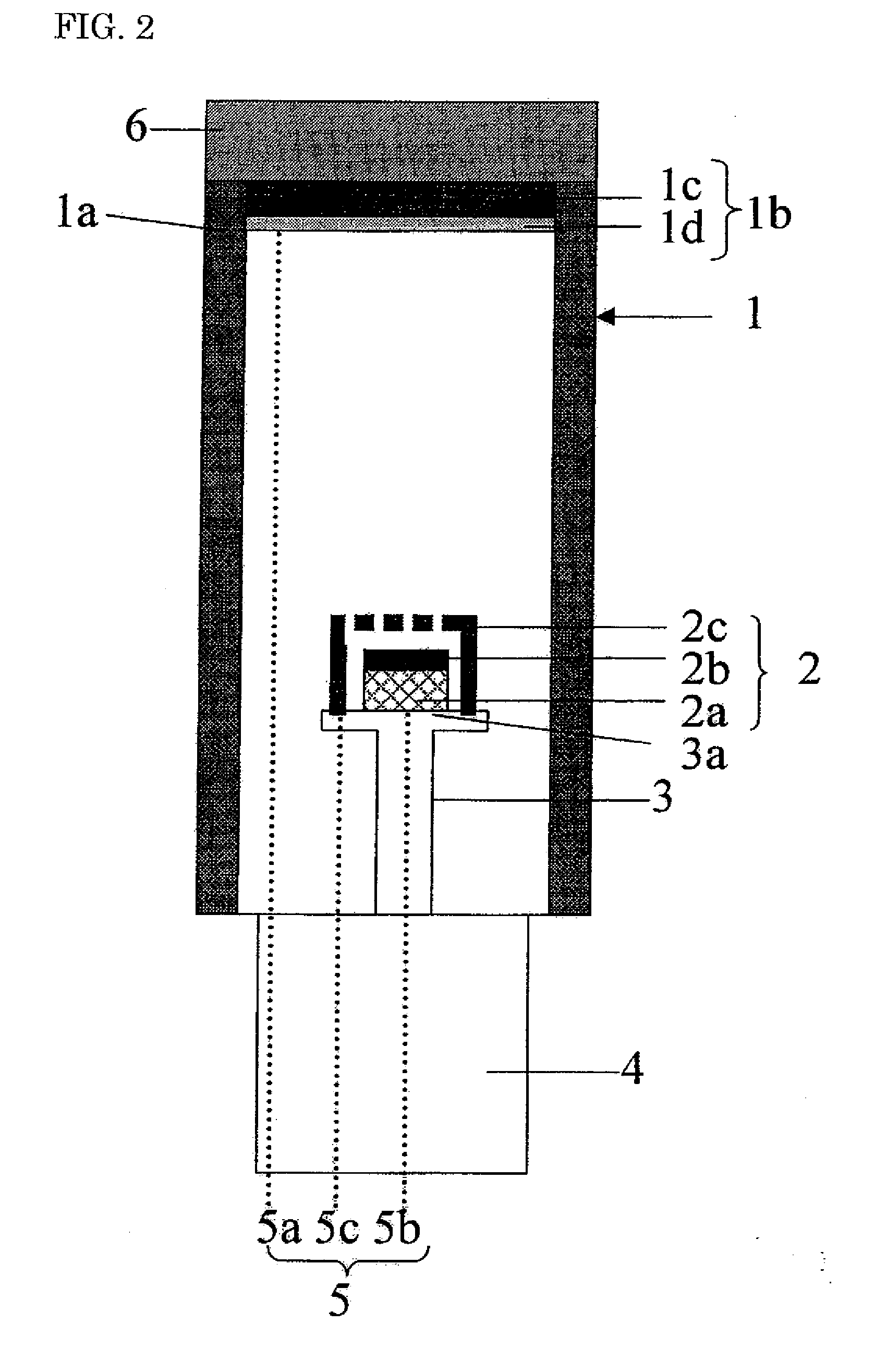
[0084]When the surface-emitting device of the present invention containing a persistent phosphor as the second phosphor is used as a backlight for a mobile phone or clock, the backlight can be lighted and screen displayed by electroluminescence when the user is operating the device, and since the backlight continues to emit light even after operation has ended and power has switched off, the backlight can save power and be viewed even in dark locations.

Problems solved by technology

Therefore, B-Cu emissions cannot be easily obtained.
However, when only a UV-emitting phosphor is used, the emission efficiency is too low and the UV-emitting phosphor cannot be used as a fluorescent lamp that emits UV light.

Method used


Image

  • Phosphor, Method For Producing Same, And Light-Emitting Device Using Same
  • Phosphor, Method For Producing Same, And Light-Emitting Device Using Same
  • Phosphor, Method For Producing Same, And Light-Emitting Device Using Same

Examples


example 1

[0105](Method for Preparing a Phosphor)

[0106]In the present embodiment, Cu is used as an activator. The procedure for preparing a Cu-activated Zn(1−x)AxS phosphor is described below.

[0107](1) Starting Material

[0108]Phosphor matrices: ZnS, MgS, CaS, SrS, and BeS having a mean grain size of 1 μm

[0109]Activator: Cu2S powder having a mean grain size of 1 μm

[0110]Co-activators: A12S3, Ga2S3, NaF, NaCl, and NaI having a mean grain size of 0.5 μm

[0111](2) Mixing

[0112]The starting materials having prescribed compositions were dispersed in various solvents and mixed for 3 hours by applying ultrasonic vibrations. The compositions in the samples are shown in TABLE 1 below. The second component in TABLE 1 refers to the Group 2A sulfide comprising the phosphor matrix. The solvents were volatilized and the starting material mixtures were dried using an evaporator in which dry argon was allowed to flow.

[0113](3) Baking

[0114]The recovered starting material mixtures were placed in a 20×200×20 mm (he...

example 2

[0128](Method for Preparing a Phosphor)

[0129]Ag was used as the activator in the present example. The procedure for preparing an Ag-activated Zn(1−x)AxS phosphor is described below.

[0130]Dispersed in ethanol were a ZnS powder used as a starting material in the amounts shown in composition tables 1 to 9; a Group 2A sulfide powder selected from BeS, MgS, CaS, SrS, and BaS powders; an Ag2S powder, which was a source for supplying the Ag activator; and a powder selected from Al2S3, Ga2S3, NaF, NaCl, NaBr, and NaI powders, which were sources for supplying the co-activators Al, Ga, F, Cl, Br, and I). Ultrasonic vibrations were then applied for 3 hours to mix the system. The values in the tables express the weight (g) of the starting material powders. However, the compositions shown in these tables are merely examples. An evaporator in which dry nitrogen or dry argon was caused to flow was thereafter used to volatilize the ethanol and dry the mixture of the starting materials. The recovere...

example 3

[0167]Ag and Au were used as activators in the present example.

[0168](Method for Preparing a Phosphor)

[0169](1) Starting Material

[0170]Phosphor matrices: ZnS, MgS, CaS, SrS, and BeS having a mean grain size of 1 μm

[0171]Activators:[0172](a) Ag source: Ag2S powder having a mean grain size of 1 μm[0173](b) Au sources: AuCl3 powder having a mean grain size of 10 μm, and Au powder having a mean grain size of 40 μm.

[0174]Co-activators: Same AuCl3 as the one above (shared with the activator), and NaCl powder having a mean grain size of 20 μm

[0175](2) Mixing

[0176]The starting material powders having prescribed doped compositions were dispersed in various solvents and mixed for 3 hours by applying ultrasonic vibrations. The solvents were volatilized and the starting material mixtures were dried using an evaporator in which dry argon was allowed to flow.

[0177](3) Baking

[0178]The recovered starting material mixtures were placed in a 20×200×20 mm (height) lidded alumina crucibles, and baked fo...


PUM


Abstract

A Phosphor represented by the general formula Zn(1−x)AxS:E,D is characterized by having a Blue-Cu light-emitting function. In the above general formula, A represents at least one group 2A element selected from the group consisting of Be, Mg, Ca, Sr and Ba; E represents an activator containing Cu or Ag; D represents a coactivator containing at least one element selected from group 3B and group 7B elements; and x represents a mixed crystal ratio satisfying 0≦x<1. The activator is preferably contained at a molar concentration equal to or higher than that of the coactivator for obtaining emission of short wavelength. As the activator, Cu and Ag are respectively used by themselves, while Ag can be suitably used in combination with Au.

Description

FIELD OF THE INVENTION[0001]The present invention relates to a light-emitting material, and particularly to a phosphor that emits light in the UV region. The present invention more particularly relates to a phosphor that is suitable for a light-emitting device as means for separating or decomposing toxic substances and sterilizing bacteria, viruses, and the like. The present invention also relates to a phosphor that uses a light-emitting device for emitting UV rays by inorganic electroluminescence (EL) to emit light, and to a method for manufacturing the phosphor. The present invention also relates to a fluorescent lamp as a light-emitting device and to a field-emission display that uses the fluorescent lamp. The present invention furthermore relates to a surface-emitting device having a surface-emitter that emits visible light rays or UV rays by inorganic EL to emit light, or excites a phosphor by the emitted visible light rays or UV rays to emit light.BACKGROUND OF THE INVENTION[0...

Claims


Application Information

Patent Timeline
IPC IPC(8): H01J1/62C09K11/54
CPCC09K11/54C09K11/565H05B33/14C09K11/586C09K11/7792C09K11/584
Inventor KAWAI, CHIHIROINOUE, RYUICHI
Owner SUMITOMO ELECTRIC IND LTD
Learn More