Motor controller and electric power steering system

Inactive Publication Date: 2008-08-14
JTEKT CORP
View PDF5 Cites 29 Cited by
  • Summary
  • Abstract
  • Description
  • Claims
  • Application Information

AI Technical Summary

Benefits of technology

[0042]According to the eighth invention, the circuit resistance including the armature winding resistance is determined from the d-axis current detection value when the d-axis current detection value is not zero. Hence, the circuit resistance including the armature winding resistance can be accurately determined without being affected by the influence of the number of armature winding flux linkages.
[0043]According to the ninth invention, when the current detection unit does not detect any current value, a calorific value is determined from the command current value, whereby the circuit resistance including armature winding resistance is determined. Hence, even when detection of a current is impossible, circuit resistance including armature winding resistance can be determined at all times. Further, in a case where circuit resistance cannot be determined at all times, torque variations suddenly arising at a point in time when determination of the circuit resistance has become possible can be reduced.
[0044]According to the tenth invention, the command current value is determined by use of the current torque constant computed by the dimension conversion section. Hence, the command current involves an individual differ

Problems solved by technology

The current sensor is large in size and hinders miniaturization of the controller of the electric power steering system.
Therefore, in relation to the motor controller included in the electric power steering system, reduction of the current sensor is considered to be a challenge to be met.
However, the former method has a drawback of, depending on the rotational position of a rotor

Method used


Image

  • Motor controller and electric power steering system
  • Motor controller and electric power steering system
  • Motor controller and electric power steering system

Examples


first embodiment

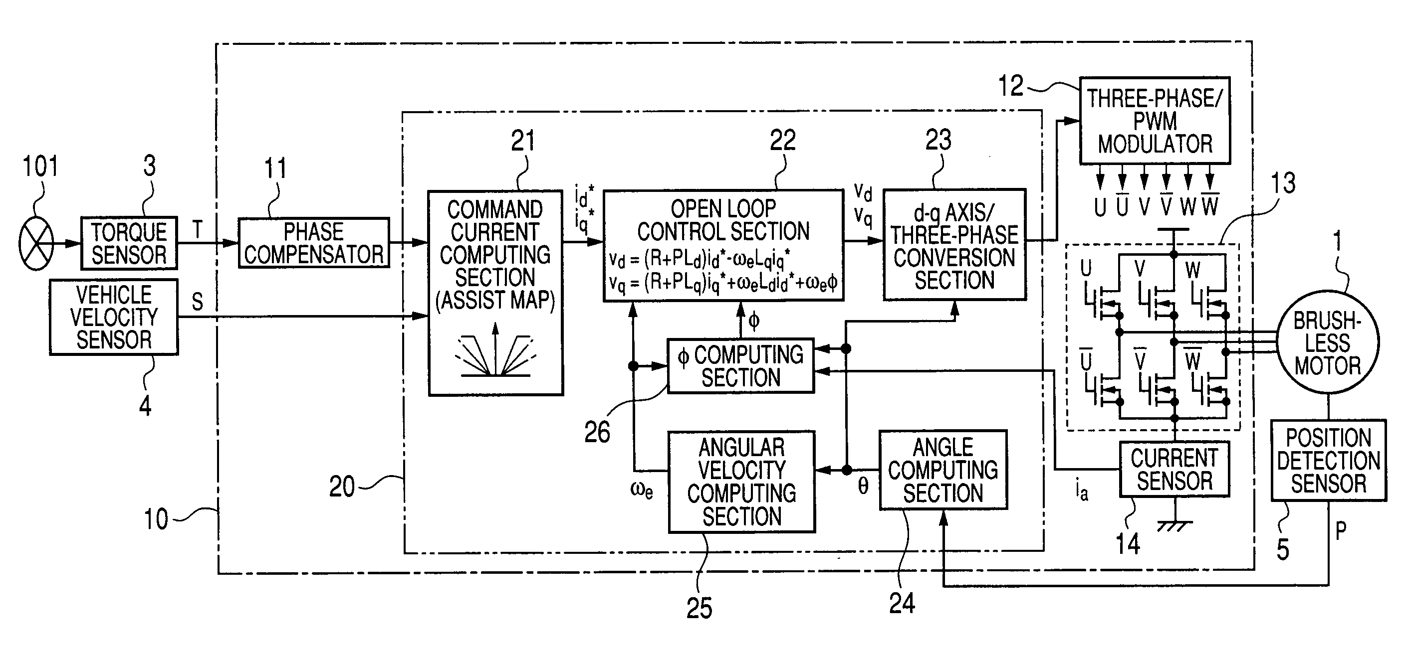
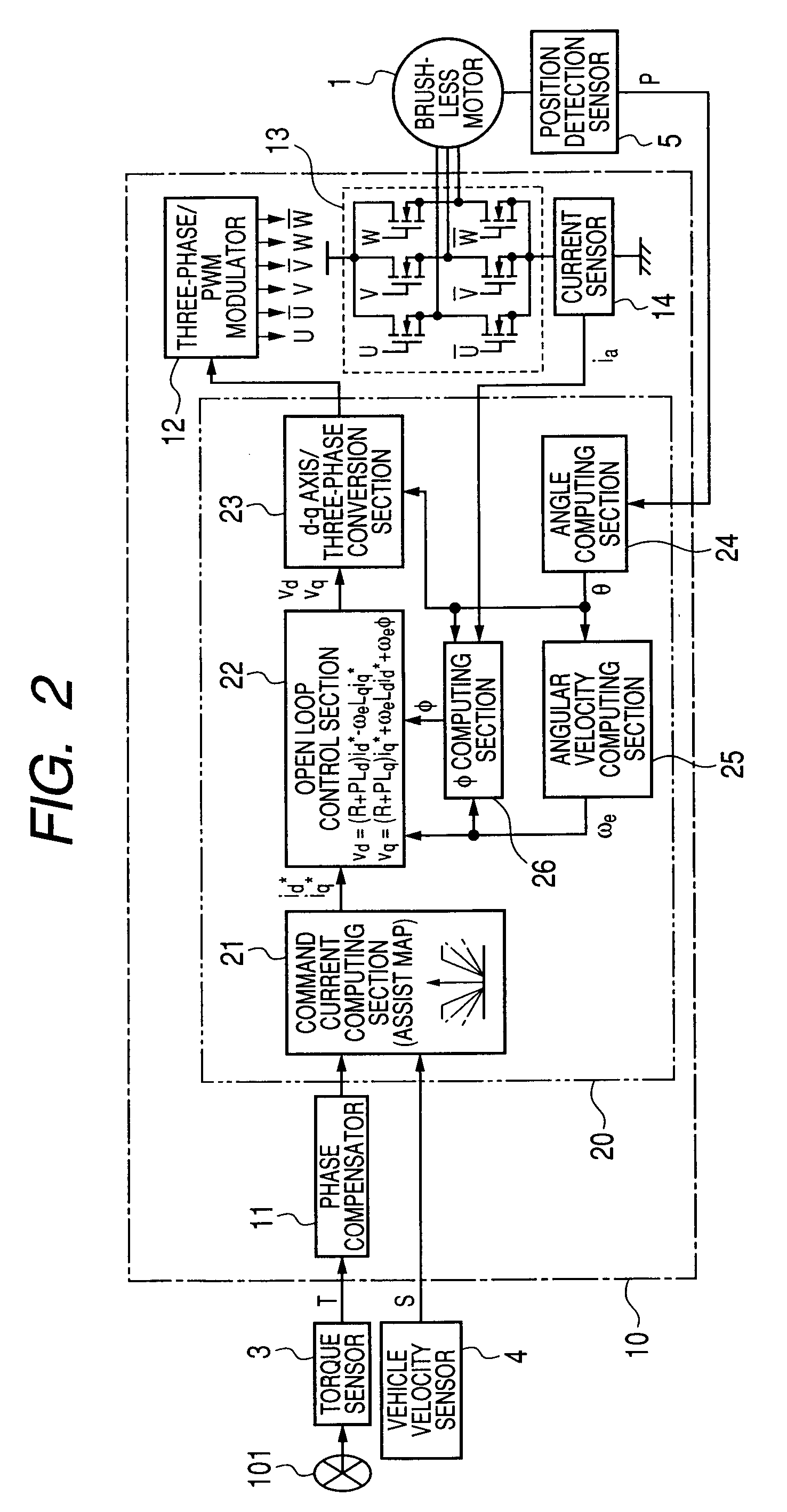
[0062]FIG. 2 is a block diagram showing the configuration of a motor controller of a first embodiment of the present invention. The motor controller shown in FIG. 2 is built by use of the ECU 10 and drives the brushless motor 1 having three-phase windings (not shown) of a “u” phase, a “v” phase, and a “w” phase. The ECU 10 has a phase compensator 11, a microcomputer 20, a three-phase / PWM (Pulse-Width Modulation) modulator 12, a motor drive circuit 13, and a current sensor 14.

[0063]The steering torque T output from the torque sensor 3, the vehicle velocity S output from the vehicle velocity sensor 4, and the rotational position P output from the position detection sensor 5 are input to the ECU 10. The phase compensator 11 compensates for the phase of the steering torque T. The microcomputer 20 acts as control unit which determines the level of a command voltage used for driving the brushless motor 1. Detailed function of the microcomputer 20 will be described later.

[0064]The three-ph...

second embodiment

[0088]FIG. 4 is a block diagram showing the configuration of a motor controller of a second embodiment of the present invention. In the motor controller of the first embodiment, the motor controller shown in FIG. 4 has a microcomputer 27 including an R computing section 28 (a parameter computing section of the invention) in place of the microcomputer 20 including the φ computing section 26. Of constituent elements of embodiments provided below, elements which are identical with those of the previously-described embodiment are assigned the same reference numerals, and their explanations are omitted.

[0089]As is the case with the φ computing section 26, the R computing section 28 is supplied with, as an input, the current value ia detected by the current sensor 14, the angle θ computed by the angle computing section 24, and the angular velocity ωe computed by the angular velocity computing section 25. The R computing section 28 determines the u-phase detection current iu and the v-phas...

third embodiment

[0098]FIG. 5 is a block diagram showing the configuration of a motor controller of a third embodiment of the present invention. The motor controller shown in FIG. 5 corresponds to the motor controller of the first embodiment in which the microcomputer 20 and the current sensor 14 are replaced with a microcomputer 30 and a current sensor 15. When the current sensor 15 operates normally, the motor controller performs feedback control operation. When the current sensor 15 has become broken, the motor controller performs open loop control.

[0099]The current sensor 15 is provided in number of one on a path through which drive currents of three phases supplied to the brushless motor 1 flow, and detects drive currents of three phases individually. The current values of three phases (hereinafter called a u-phase detection current iu, the v-phase detection current iv, and the w-phase detection current iw) detected by the current sensor 15 are input to the microcomputer

[0100]When compared with...


PUM


Abstract

An angle computing section determines an angle of a rotor, and an angular velocity computing section determines angular velocity of the rotor. A command current computing section determines, from a steering torque and vehicle velocity, command currents and taken along d-q axes. An open loop control section determines, from command currents and angular velocity, command voltages taken along the d-q axes in accordance with motor circuit equations. A d-q axis/three-phase conversion section converts the command voltages into command voltages of three phases. A φ computing section determines the number of armature winding flux linkages included in a motor circuit equation from a q-axis command voltage, the current value detected by a current sensor, and the angular velocity. Circuit resistance including armature winding resistance R included in the motor circuit equation may also be determined by means of the same configuration.

Description

BACKGROUND OF THE INVENTION[0001]1. Field of the Invention[0002]The present invention relates to a motor controller and an electric power steering system equipped with the motor controller.[0003]2. Related Art[0004]There has hitherto been known an electric power steering system which provides a steering mechanism of a vehicle with steering assist power by driving an electric motor in accordance with steering torque applied to a handle (a steering wheel) by a driver. Although a brush motor has hitherto been used for an electric motor of the electric power steering system, a brushless motor is recently used, as well, from the viewpoint of an improvement in reliability and durability and a reduction in inertia.[0005]In general, in order to control a torque generated in the motor, the motor controller detects an electric current flowing into the motor, and performs PI control (proportional integration control) in accordance with a difference between an electric current to be supplied to...

Claims


Application Information

Patent Timeline
IPC IPC(8): H02P23/00G05B11/42
CPCB62D5/046H02P21/04B62D5/0487B62D5/0484
Inventor UEDA, TAKESHINAGASE, SHIGEKISUMASU, HIROSHI
Owner JTEKT CORP
Why Eureka
Try Eureka