
Method and apparatus for tuning an active filter

a technology of active filters and filter circuits, applied in electrical equipment, transmission, electric vehicles, etc., can solve the problems of increasing the power consumption of the filter circuit, and the inability of the mosfet to provide a sufficient variable control range to compensa

Active Publication Date: 2008-08-14
MEDIATEK SINGAPORE PTE LTD SINGAPORE
View PDF11 Cites 23 Cited by
  • Summary
  • Abstract
  • Description
  • Claims
  • Application Information

AI Technical Summary

Benefits of technology

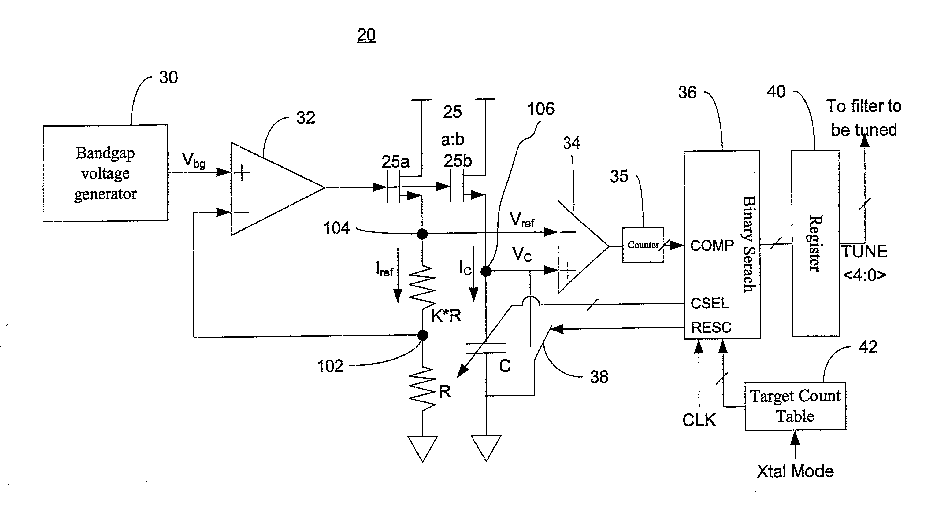
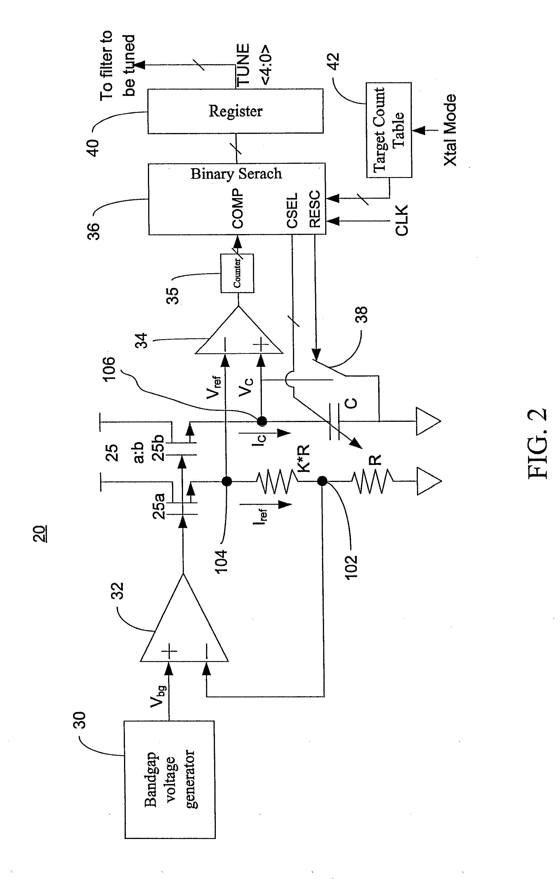
The invention is a tuning apparatus and method for adjusting the capacitance of a capacitor to comply with the desired RC time constant. The apparatus includes a resistor-capacitor circuit, a voltage generator, a current replicating unit, a comparator, a counter, and an adjustment unit. The method involves providing a target count value associated with a predetermined RC time constant, applying a constant reference voltage to a resistor, generating a second reference voltage based on the ratio of the two resistors, replicating a current based on the constant voltage, comparing a charging voltage as the current charges a variable capacitor with the second constant reference voltage, counting the number of cycles of a clock signal with a counter as the current charges the variable capacitor, and adjusting the capacitance of the variable capacitor to comply with the predetermined RC time constant based on the number of cycles of the clock signal and the target count value. The technical effect of this invention is to provide a reliable and efficient way to adjust the capacitance of a capacitor to achieve the desired RC time constant.

Problems solved by technology

However, this solution conflicts with the advantages offered by integrated circuits, such as low cost and small form-factor (few or none external components) of the filter circuit.
This solution, however, needs a continuous input signal for the MOSFET and thus causes an increase of power consumption of the filter circuit.
Moreover, this approach is disadvantageous when a low supply voltage is used (e.g. as low as 1 V); since the MOSFET, in general, requires a large sub-1V threshold voltage to be conductive, such that the MOSFET cannot provide a sufficient variable control range to compensate for the large variations of the active filter.

Method used


Image

  • Method and apparatus for tuning an active filter
  • Method and apparatus for tuning an active filter
  • Method and apparatus for tuning an active filter

Examples


Embodiment Construction

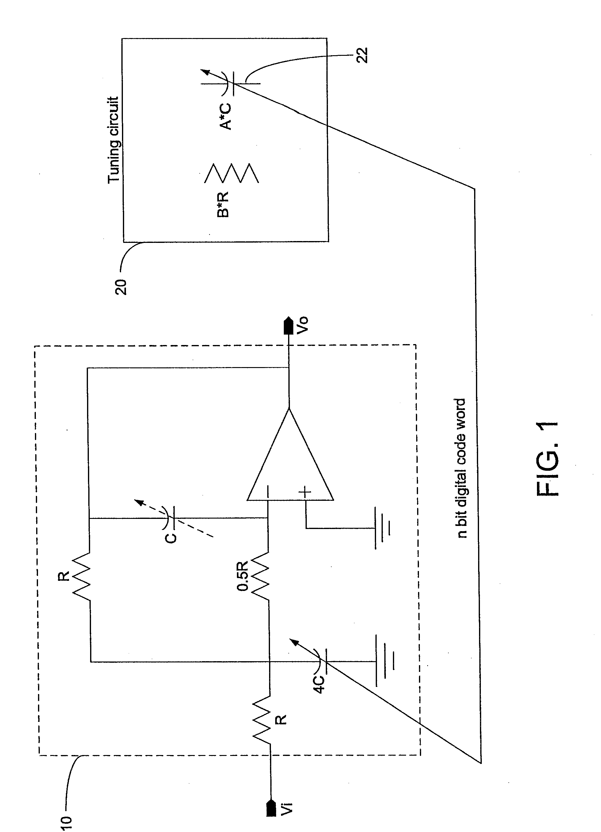
[0019]Referring to FIG. 1, as shown is a block diagram of a tuning circuit 20 for tuning an RC circuitry 10 in accordance with the preferred embodiment of the present invention. The RC circuitry 10 comprises resistors and capacitors which are all made on a wafer and associated with a variable capacitor 22 of the tuning circuit 20. When both tuning circuit and the active filter are implemented in the same integrated circuit, variations in capacitors (resistors) will generally directly track with variations in capacitor (resistor) of the tuning circuit provided that all of the capacitors (resistors) are fabricated to be of the same type and physical orientation. Therefore, the RC time constants of both circuits are directly proportional. With good matching, each capacitance value of capacitors on the same wafer has almost identical error of capacitance. Thus the tuning circuit 20 can measure any capacitor on the wafer to determine the capacitance error and feedback such error to compe...


PUM


Abstract

A tuning circuit for tuning an active filter includes a resistor-capacitor circuit comprising a variable capacitor and a resistor equivalent to a first resistor and a second resistor serially connected to the first resistor, a voltage generator for providing a constant reference voltage to the first resistor, a current replicating unit for replicating a current based on the constant reference voltage, a comparator for comparing a charging voltage as the current is charging a variable capacitor with the constant reference voltage, a counter for counting a number of cycles of a clock signal until the charging voltage reaches the constant reference voltage, a adjustment unit for calibrating a capacitance of the variable capacitor based on the number of cycles of a clock signal and a target count value associated with a predetermined RC time constant.

Description

BACKGROUND OF THE INVENTION[0001]1. Field of the Invention[0002]The invention relates to a method and apparatus for tuning an active filter, more particularly to a method and apparatus for tuning the 3-dB corner frequency of filters to approach a constant characteristic.[0003]2. Description of the Related Art[0004]As development of integrated circuitry technology is accelerated, necessary functions are integrated within a single chip. In particular, analog filter circuits implemented by capacitors and resistors are widely used in electronics or communication products. In the design and manufacture of active continuous-time filter, the frequency response is directly proportional to variation of the values of resistors and capacitors. As is well known in the art, the use of capacitors and resistors generates RC-product shifts on account of variations in temperature, supply voltage, and manufacturing process. Unavoidably, variation in manufacturing process and variations during operati...

Claims


Application Information

Patent Timeline
Patent Type & Authority Applications(United States)
IPC IPC(8): H03K5/00H02J7/00
CPCH03H11/1291H03H2210/043H03H2210/021
Inventor DHARMALINGGAM, RAWINDERCHIU, CHINQ-SHIUN
Owner MEDIATEK SINGAPORE PTE LTD SINGAPORE
Learn More