Electro Active Compression Bandage

a compression bandage and active technology, applied in the direction of massage belts, ligaments, therapy, etc., can solve the problems of bandage being associated with numerous problems, unable to fully understand the underlying pressure, and unable to achieve the effect of improving the pressure profil

Active Publication Date: 2008-08-14
SWELLING SOLUTIONS
View PDF16 Cites 53 Cited by
  • Summary
  • Abstract
  • Description
  • Claims
  • Application Information

AI Technical Summary

Benefits of technology

[0012]The object of the present invention is therefore to alleviate the above-mentioned problems and thus accomplish improved pressure profiles in terms of a well-defined location, distribution and magnitude of the pressure that is applied to the outside a human body part.

Problems solved by technology

For instance, lymphoedema is a condition where the lymphatic system of a patient has been compromised, thereby resulting in a buildup of lymphatic fluids and proteins in one or more extremities.
Moreover, the underlying pressure is unknown after application, and the bandages are there to prevent the limb from further expanding and to breakup proteins with the help of patient movement.
Nevertheless, these bandages are associated with numerous problems.
The bandages are also bulky and hot to wear due to the many layers applied to the limb, and therefore the bandages cannot be worn under clothing.
Naturally, the therapy for the patient is limited in that the multi-layered lymphatic bandages cannot actively pressurize the body.
Hence, also in this case, the pressure application is static and a qualified person must apply the bandages to ensure that an appropriate pressure is accomplished, particularly since there is no convenient way to accurately measure the pressure applied to the limb.
However, the pneumatic compression pump devices are relatively inefficient, and therefore cannot operate from batteries for any significant length of time.
Thus, the device can only be used for comparatively short durations before it becomes too uncomfortable for the patient.
Additionally, the device is noisy, the air-pressure measurements used to infer pressure applied to the limb can be inaccurate, and unintentionally high pressure levels may harm the patient.
Such massage techniques are highly technical and require significant training to perform.
However, the solution is still inadequate for many medical applications.
For instance, the skin of a patient is often compromised due to various medical conditions.
In addition, the health of the patient's skin may lack elasticity, strength and resilience.
For instance, if highly localized pressures are applied for long periods of time, the tissues can tear and / or pressure ulcers may be formed.
Moreover, if subjected to repeated rubbing, the skin can chafe, or even rip.
Additionally, the medical treatments often require that the garments be worn for prolonged periods of time during which pressure and / or repeated pressure pulsation may be applied.
Such activities further increase the risk of damage being caused to the patient's skin.
Interestingly, this document does not address the way in which pressure application is smoothed out over the limb.
Instead, it appears most likely that the proposed polymer strips, which are relatively far spaced from one another risk to cause pressure ulcers and tissue damages.
Moreover, improper materials are selected for the intended application because none of the polymer strips are capable of providing the high forces required in the thrombophlebitis treatment.

Method used


Image

  • Electro Active Compression Bandage
  • Electro Active Compression Bandage
  • Electro Active Compression Bandage

Examples


first embodiment

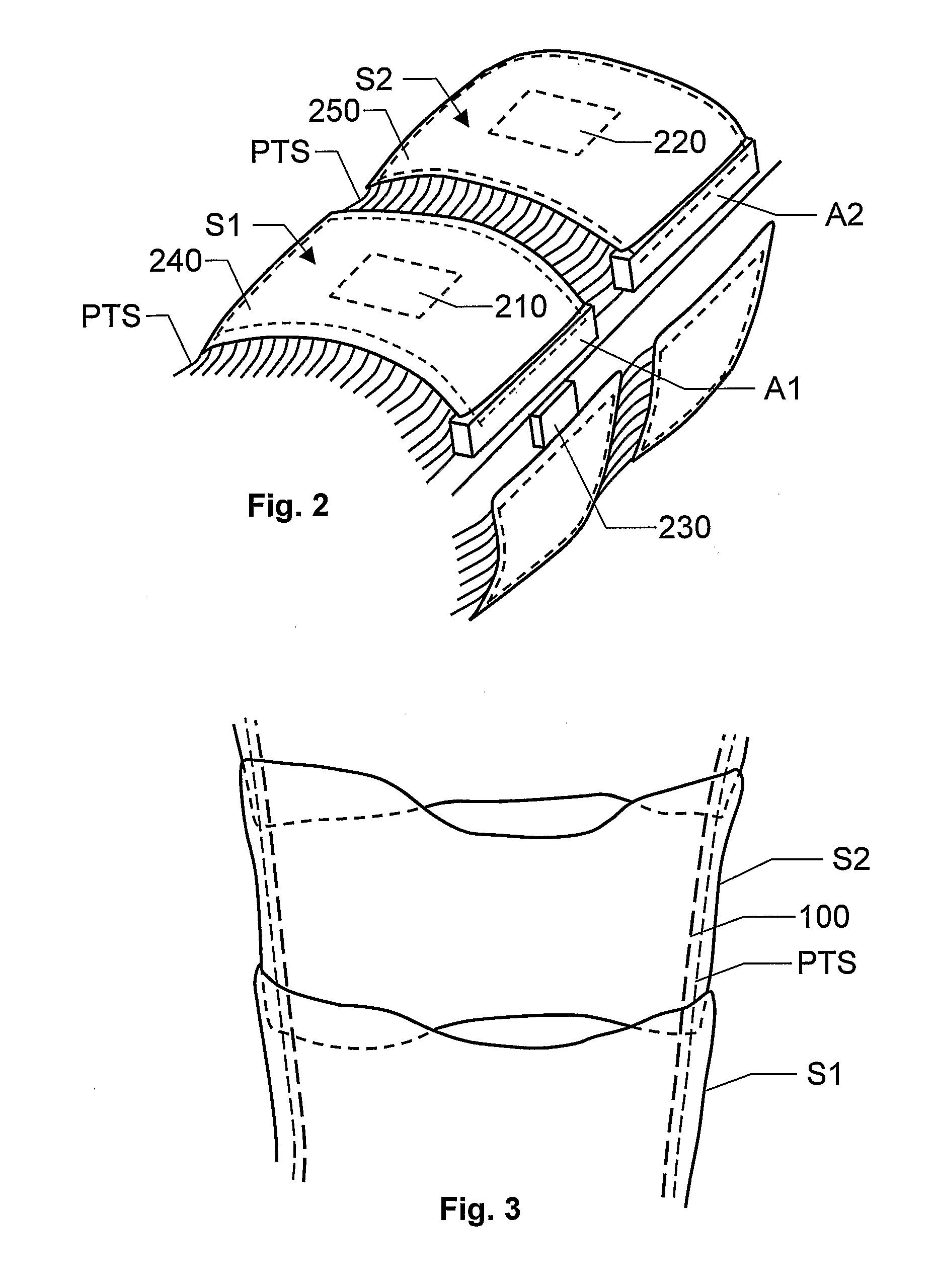
[0068]FIG. 2 shows a perspective view of a device according to the invention. Here, two segments S1 and S2 are shown. However, according to the invention, the device may include any number of segments larger than two. The pressure transition system PTS is at least positioned between the first and second segments S1 and S2. Thereby, the pressure transition system PTS may bridge over pressure profiles and tension forces from one segment to another, i.e. from S1 to S2, from S2 to S1, etc. Here, different degrees of coupling between the segments may be attained depending upon which fiber directions that are chosen for a fabric used in the pressure transition system PTS.

[0069]As mentioned above, according to the invention, each segment S1 and S2 includes an actuator A1 and A2 respectively. Here, the segments S1 and S2 include a respective strap member 240 and 250, and the actuators A1 and A2 are located at one end of each segment. The actuators A1 and A2 are further attached to the strap...

second embodiment

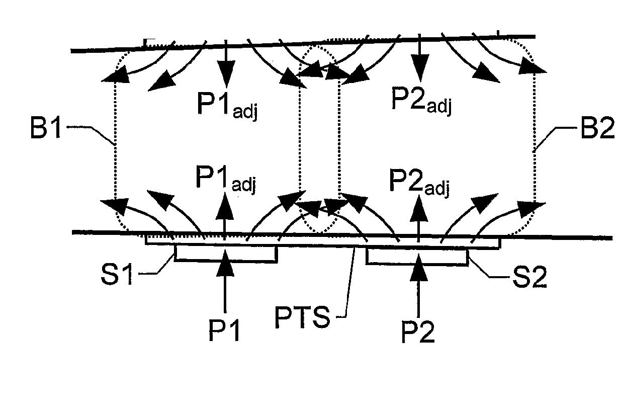
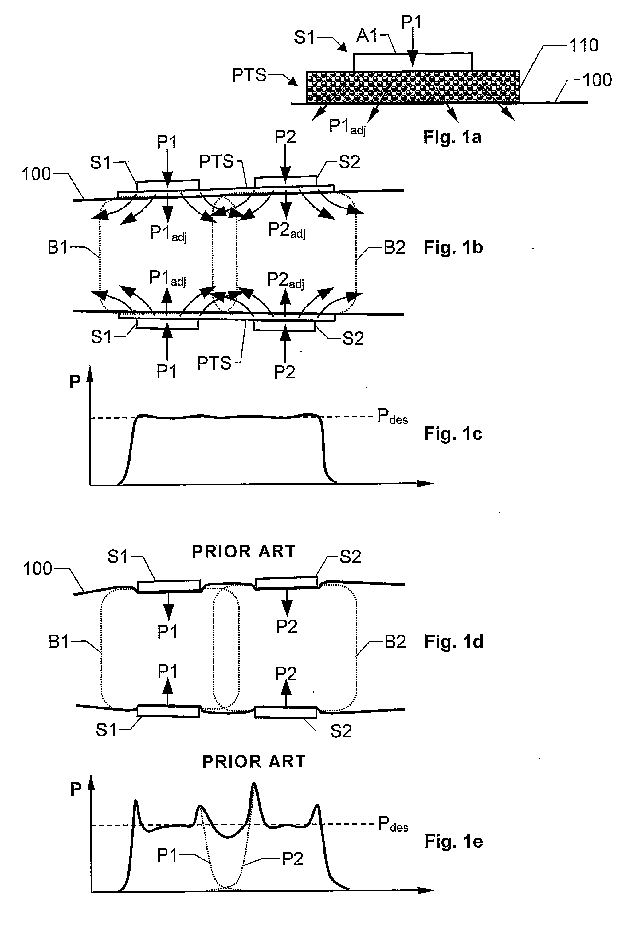
[0075]FIG. 3 shows a perspective view of a device according to the invention. Here, each of a number of segments S1, S2, etc. at least partially encloses a body part 100. Moreover, the segments are arranged such that a portion of one segment S1 covers a portion of a neighboring segment S2, and so on. Thereby, analogous to the embodiment described above with reference to FIG. 1b, relatively smoothed-out, or fuzzy, pressure profiles may be applied to the body part 100 in response to control signals in respect of the segments S1 and S2. Moreover, to redistribute these pressure profiles a pressure transition system PTS is located between the segments and the body part 100. Preferably, the pressure transition system PTS has a low-friction surface towards the segments S1 and S2, so that smooth tangential movements of the segments S1 and S2 are allowed relative to the pressure transition system PTS.

[0076]FIGS. 4a-b show two cross-section views of one embodiment of the proposed pressure tra...


PUM


Abstract

The proposed device includes two segments adapted to enclose a body part in a form-fitting manner. Each segment contains an electroactive-material-based actuator, which is adapted to receive an electrical control signal and in response thereto adjust the actuator's morphology, so as to cause the segment to apply a basic pressure profile to the body part. A pressure transition is adapted to redistribute the basic pressure profiles between the first and second segments. A control signal in respect of the first segment causes the pressure transition system to apply a first adjusted pressure profile to at least part of the second portion of the body part, and vice versa, a control signal in respect of the second segment causes the pressure transition system to apply a second adjusted pressure profile to at least a part of the first portion of the body part.

Description

THE BACKGROUND OF THE INVENTION AND PRIOR ART[0001]The present invention relates generally to the application of pressure profiles to living tissues. More particularly the invention relates to a device for exerting an external pressure to a human body part according to the preamble of claim 1 and a therapeutic garment according to the preamble of claim 34.[0002]External pressure profiles may be applied to living tissues, e.g. of a person's limb, in order to attain various effects with respect to these tissues. Perhaps the most well known example is the so-called G-suit worn by a pilot to restrict the blood circulation in his / her lower body parts under certain conditions, and thus reduce the risk that an insufficient amount of blood is fed to the pilot's head.[0003]However, also in the medical field there are many examples of situations in which it is relevant / desirable to apply an external pressure to a part of the human body, in order to cure or mitigate a disease or condition. For...

Claims


Application Information

Patent Timeline
Patent Type & Authority Applications(United States)
IPC IPC(8): A61F13/00
CPCA61B17/1325A61H23/0245A61H2011/005A61H2201/50A61F13/085A61H7/00A61H1/008A61H2201/165A61B2017/00398A61B2017/00871
Inventor LARSON, TOMASTOTH, LANDY
Owner SWELLING SOLUTIONS
Why Eureka
Try Eureka