
Display device, electronic device having the same, and method thereof

a technology of electronic devices and display devices, applied in the direction of identification means, instruments, computing, etc., can solve the problems of space becoming occupied and the electrical device is vulnerable to static electricity, so as to reduce the number of terminals for transmitting, prevent electrostatic damage, and reduce the spatial limitation of integration chips and mpu.

Active Publication Date: 2008-08-14
SAMSUNG DISPLAY CO LTD
View PDF6 Cites 6 Cited by
  • Summary
  • Abstract
  • Description
  • Claims
  • Application Information

AI Technical Summary

Benefits of technology

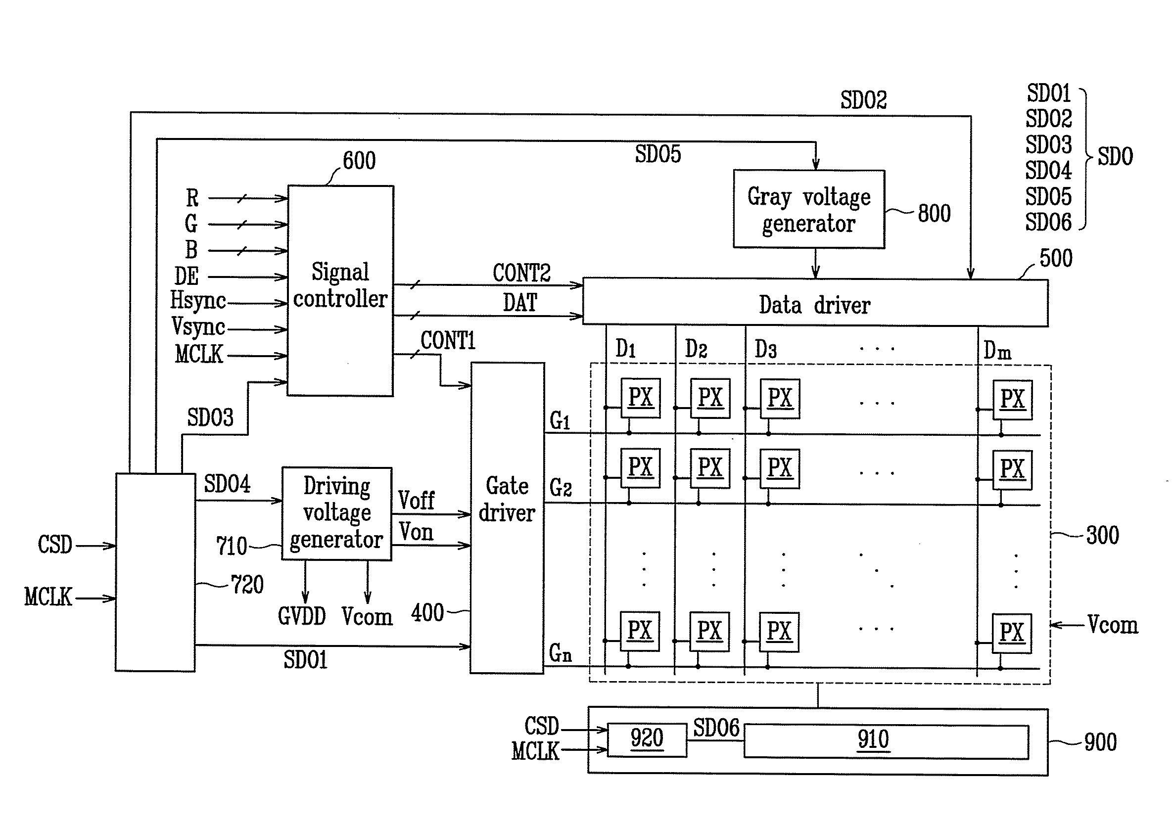
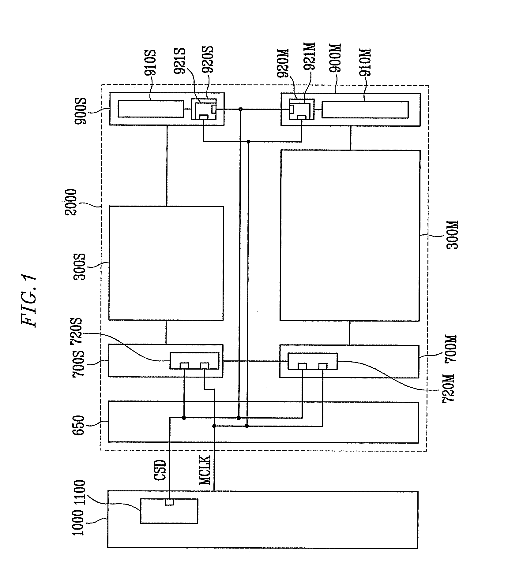
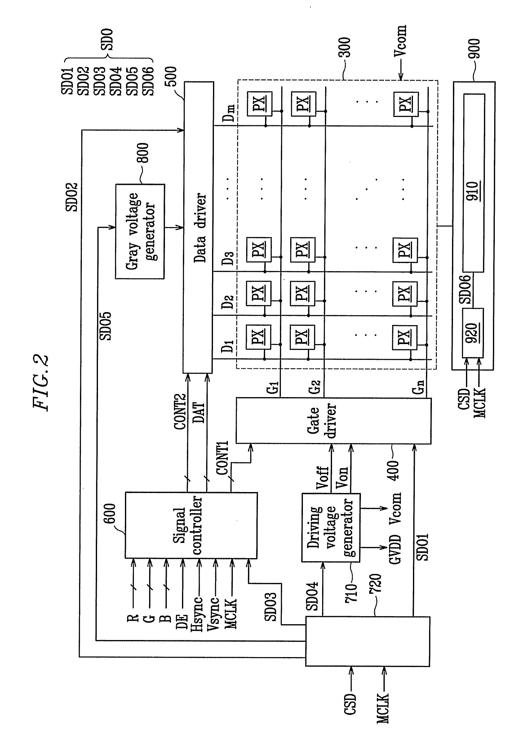
[0011]The present invention reduces the number of terminals for transmitting and receiving signals between an integration chip and a microprocessor unit (“MPU”) to reduce a spatial limitation of the integration chip and the MPU, and to prevent electrostatic damage (“ESD”) in a display device and an electronic device including the display device.

Problems solved by technology

However, as the number of terminals increases, space becomes limited, and the electrical device is vulnerable to static electricity.

Method used


Image

  • Display device, electronic device having the same, and method thereof
  • Display device, electronic device having the same, and method thereof
  • Display device, electronic device having the same, and method thereof

Examples


Embodiment Construction

[0029]The present invention will be described more fully hereinafter with reference to the accompanying drawings, in which exemplary embodiments of the invention are shown. As those skilled in the art would realize, the described embodiments may be modified in various different ways, all without departing from the spirit or scope of the present invention.

[0030]In the drawings, the thickness of layers, films, panels, regions, etc., are exaggerated for clarity. Like reference numerals designate like elements throughout the specification. It will be understood that when an element such as a layer, film, region, or substrate is referred to as being “on” another element, it can be directly on the other element or intervening elements may also be present. In contrast, when an element is referred to as being “directly on” another element, there are no intervening elements present.

[0031]It will be understood that, although the terms first, second, third etc. may be used herein to describe v...


PUM

PropertyMeasurementUnit
electric fieldaaaaaaaaaa
voltageaaaaaaaaaa
interfaceaaaaaaaaaa

Abstract

An electronic device includes a central processing unit (“CPU”), first and second display panels, and first and second display panel drivers. The CPU provides an image signal and an input control signal. The first and second display panels respectively display images. The first and second display panel drivers drive the first and second display panels according to the image signal and the input control signal. The CPU includes an interface transmission unit outputting an interface signal to control the first and second display panel drivers. The first and second display panel drivers respectively include first and second interface receiving units receiving the interface signal from the interface transmission unit. The interface signal includes a display panel selection bit and a data bit.

Description

[0001]This application claims priority to Korean Patent Application No. 10-2007-0014370, filed on Feb. 12, 2007, and all the benefits accruing therefrom under 35 U.S.C. §119, and the contents of which in its entirety are herein incorporated by reference.BACKGROUND OF THE INVENTION[0002](a) Field of the Invention[0003]The present invention relates to a display device, an electronic device having the same, and a method thereof. More particularly, the present invention relates to a display device having spatial limitations solved and reducing electrostatic damage (“ESD”) therein, an electronic device having the display device, and a method of controlling the electronic device.[0004](b) Description of the Related Art[0005]In recent years, as a substitute for heavy and large cathode ray tubes (“CRTs”), flat panel displays, such as organic light emitting diode (“OLED”) displays, plasma display panels (“PDPs”), and liquid crystal displays (“LCDs”) have been actively developed.[0006]The PDP...

Claims


Application Information

Patent Timeline
Patent Type & Authority Applications(United States)
IPC IPC(8): G06F3/00G02F1/133G02F1/1347G09F9/00G09G3/20G09G3/34G09G3/36
CPCG06F3/044G06F3/0412G09G3/20G09G3/32G09G3/36H04B1/40
Inventor KIM, DEUK-SOOLEE, KUN-BINAHN, HYEONG-CHEOLLEE, DONG-WON
Owner SAMSUNG DISPLAY CO LTD
Learn More