Direct Injection Internal Combustion Engine and Injector Used for Direct Injection Internal Combustion Engine

a technology of internal combustion engine and injector, which is applied in the direction of machines/engines, electrical control, mechanical equipment, etc., can solve the problems of power reduction and fuel evaporation degradation

Inactive Publication Date: 2008-08-21
HITACHI LTD
View PDF0 Cites 22 Cited by
  • Summary
  • Abstract
  • Description
  • Claims
  • Application Information

AI Technical Summary

Benefits of technology

[0015]In accordance with the present invention, combustion has been improved by providing another

Problems solved by technology

However, if much fuel is oriented toward the ignition plug, fuel sprays of the injector adhere to the s

Method used


Image

  • Direct Injection Internal Combustion Engine and Injector Used for Direct Injection Internal Combustion Engine
  • Direct Injection Internal Combustion Engine and Injector Used for Direct Injection Internal Combustion Engine
  • Direct Injection Internal Combustion Engine and Injector Used for Direct Injection Internal Combustion Engine

Examples


first embodiment

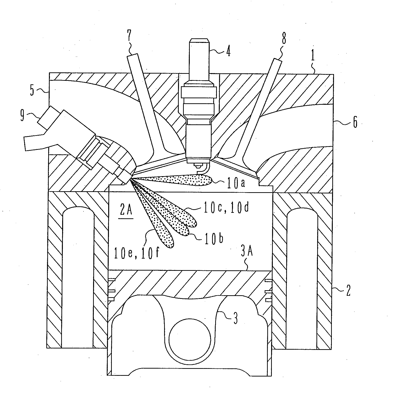
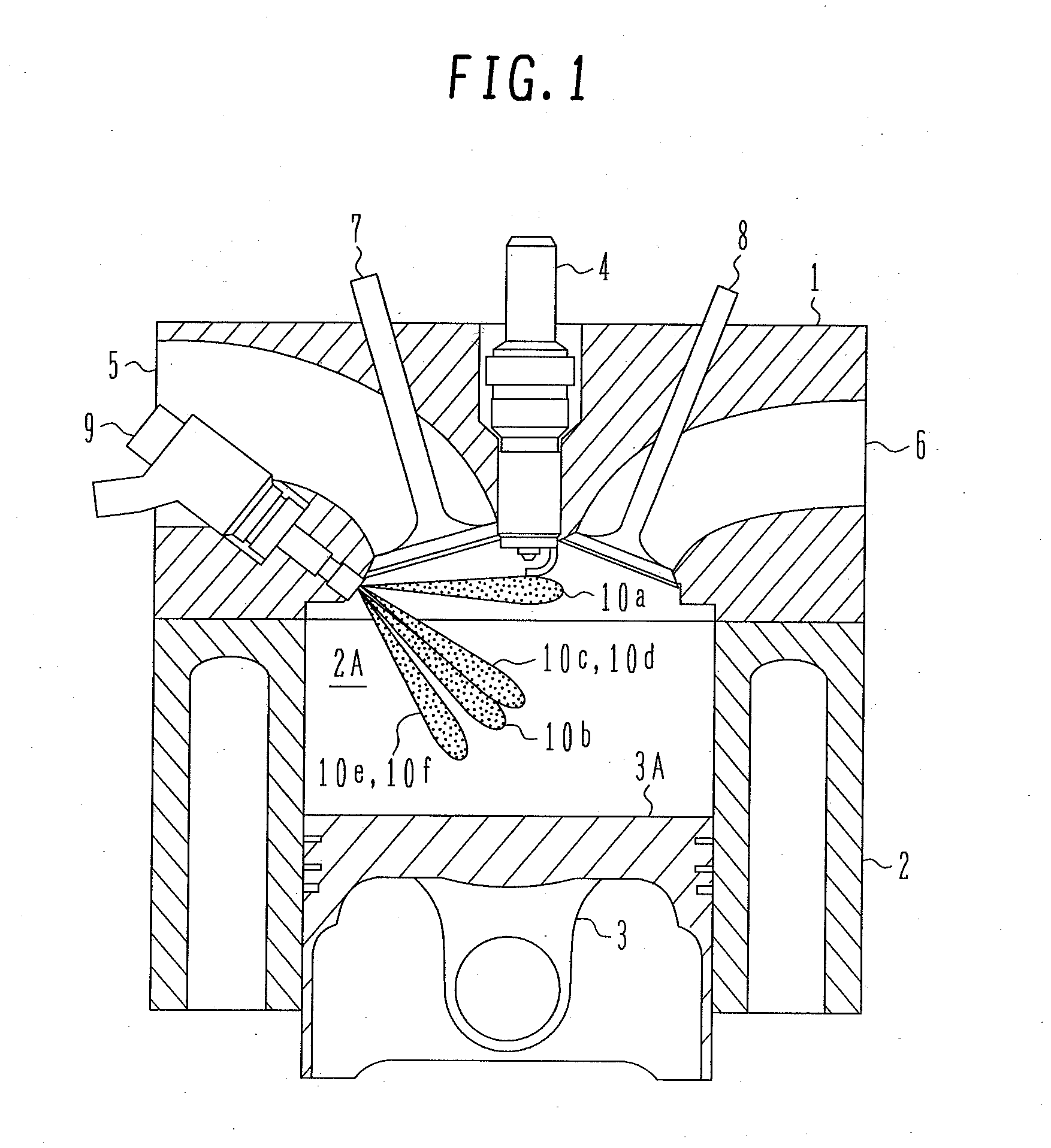
[0052]A configuration of a direct injection engine according to a first embodiment is schematically shown in FIG. 1.

[0053]A combustion chamber 2A is composed of a cylinder head 1, a cylinder block 2, and a piston 3 inserted into the cylinder block 2. An ignition plug 4 is provided at the center top of the combustion chamber 2A. A suction pipe 5 and an exhaust pipe 6 open into the combustion chamber 2A, which are provided with a suction valve 7 and an exhaust valve 8, respectively, to open and close each opening. An injector 9 is provided on the suction side in the combustion chamber 2A so as to inject fuel directly into the combustion chamber 2A, and fuel sprays 10a to 10f are injected.

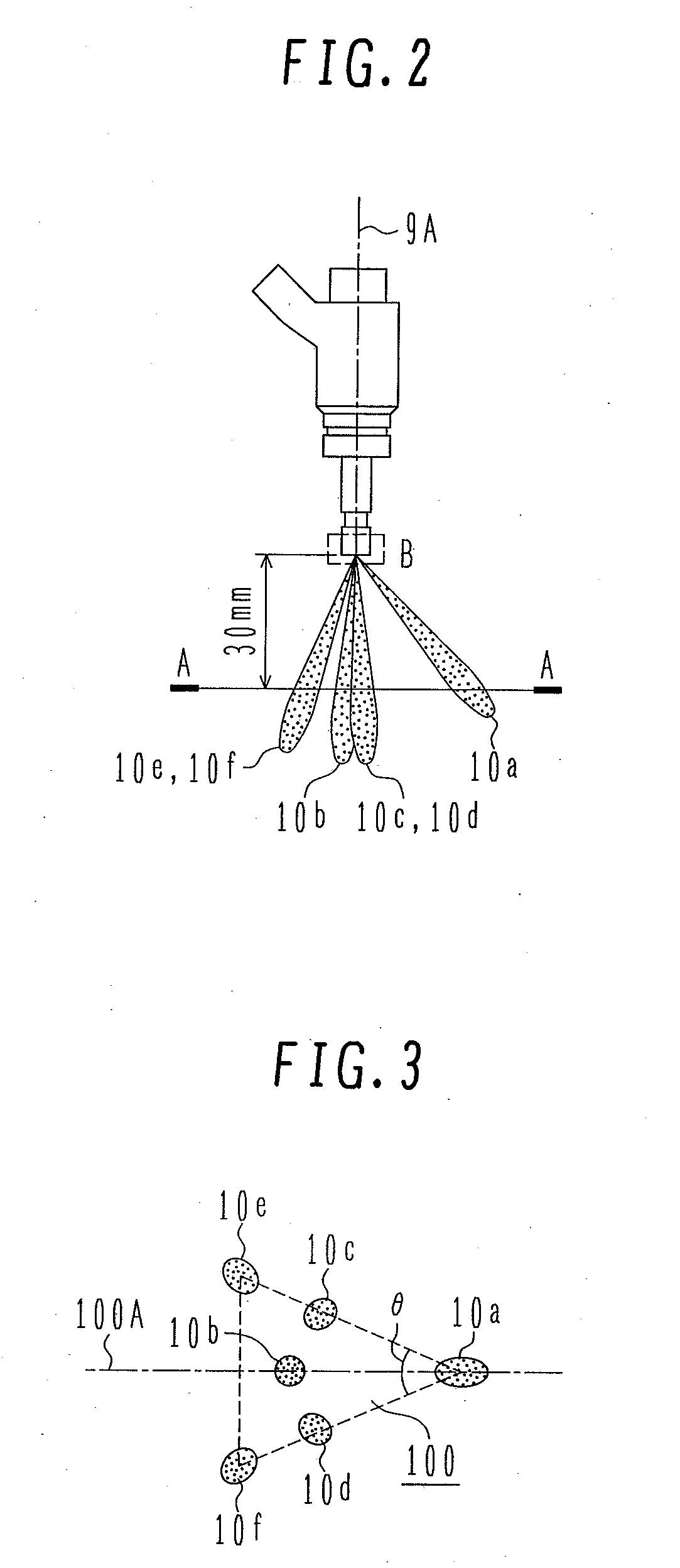
[0054]The shapes of fuel sprays injected from the injector 9 used by the first embodiment are shown in FIGS. 2 and 3, and a nozzle in an enlarged manner in FIG. 4. FIGS. 2 and 3 show external shapes of fuel sprays injected into a free space having an atmospheric pressure equalized to the barometric pr...

second embodiment

[0064]A second embodiment will be explained below. With the specifications according to the second embodiment, the air volume displacement per cylinder is 400 cc and the bore diameter is 80 mm like the first embodiment. However, a supercharger is provided resulting in an actual air volume displacement of 400 cc or more. The flow rate of the injector is 800 cc / min under a 7 MPa fuel pressure condition.

[0065]The nozzle in an enlarged manner is shown FIG. 6. FIG. 7 shows the shapes of fuel sprays taken along the AA line at 30mm below the nozzle holes at 1 ms after fuel injection under a 11 MPa fuel pressure condition. Nozzle holes 13 are circumferentially provided at the end of the injector 9. The shapes of fuel sprays injected from the nozzle holes 13a to 13f of FIG. 6 correspond to fuel sprays 12a to 12f of FIG. 7. The injector 9 is located so that the fuel spray 12a is on the side of the ignition plug 4 as shown in FIG. 8.

[0066]In accordance with the present embodiment, the diameter...

third embodiment

[0067]A third embodiment will be explained below. With the specifications according to the third embodiment, the air volume displacement per cylinder is 400 cc and the bore diameter is 80 mm like the first embodiment. The flow rate of the injector under a 7 MPa fuel pressure condition is 650 cc / min.

[0068]The nozzle in an enlarged manner according to the present embodiment is shown in FIG. 9. FIG. 10 shows the shapes of fuel sprays taken along the AA line at 30 mm below the nozzle holes at 1 ms after fuel injection under a 11 MPa fuel pressure condition. Nozzle holes 36 are circumferentially provided at the end of the injector 9. The shapes of fuel sprays injected from the nozzle holes 36a to 36h of FIG. 9 correspond to the fuel sprays 35a to 35h of FIG. 10. The injector 9 is located so that the fuel spray 36a is on the side of the ignition plug 4 as shown in FIG. 11.

[0069]In accordance with the present embodiment, the nozzle holes 36a to 36h have the same diameter to perform equal f...


PUM


Abstract

It is necessary to attain the combustion stability when performing ignition retarding in order to reduce exhaust gas and raise the exhaust gas temperature under a cold start condition, as well as soot reduction under a fully open throttle valve condition.
An injector according to the present invention comprises: a plurality of fuel passages having an axis line inclined with respect to a valve operation axis line at a nozzle end; wherein inclined axis lines of at least three of the fuel passages have a spreading angle, none of them intersecting with each other, and three injection points are formed in a plane perpendicular to a valve operation axis line to form a triangle; and wherein at least one center-oriented fuel passage having an injection point around the center of the triangle is provided.

Description

BACKGROUND OF THE INVENTION[0001]1. Field of the Invention[0002]The present invention relates to an engine with direct fuel injection into the cylinder (hereinafter referred to as combustion chamber), so-called a direct injection internal combustion engine (hereinafter referred to as engine), which is provided with an injector having a plurality of fuel injection nozzles (hereinafter referred to as injector).[0003]2. Description of the Related Art[0004]JP-A-8-312352 discloses a technique of attaining efficient premixed combustion in a direct injection engine which is provided with an injector having a plurality of nozzles (hereinafter referred to as multi-hole injector). With the technique, at least one fuel spray is oriented toward the upper direction than the injector and at least one of the remaining fuel sprays toward the piston to form a homogeneous air-fuel mixture.[0005]Further, JP-A-2005-98120 discloses a technique of improving the fuel efficiency by orienting a plurality of...

Claims


Application Information

Patent Timeline
IPC IPC(8): F02B3/00
CPCF01N3/10F01N11/00F02B23/104F02B23/105F02B2023/103Y02T10/125F02D41/3029F02M61/1806F02M61/1826F02M61/1853F02M63/0225F02D41/064Y02T10/12
Inventor KIHARA, YUSUKESHIRAISHI, TAKUYATUCHITA, KENJITUCHITA, SUMIENATSUI, HIROYUKIFUJII, HIROSHISEKINE, ATSUSHI
Owner HITACHI LTD
Why Eureka
Try Eureka