Toner recovery apparatus, process cartridge, and image forming apparatus

a technology which is applied in the field of toner recovery apparatus and process cartridge, can solve the problems of waste toner, waste toner efficiency, and inability to realize the performance of the process cartridge with a vertical structure for further reducing the size in the above described related art, and achieve the effect of effective transportation of toner

Active Publication Date: 2008-08-21
RICOH KK
View PDF29 Cites 50 Cited by
  • Summary
  • Abstract
  • Description
  • Claims
  • Application Information

AI Technical Summary

Benefits of technology

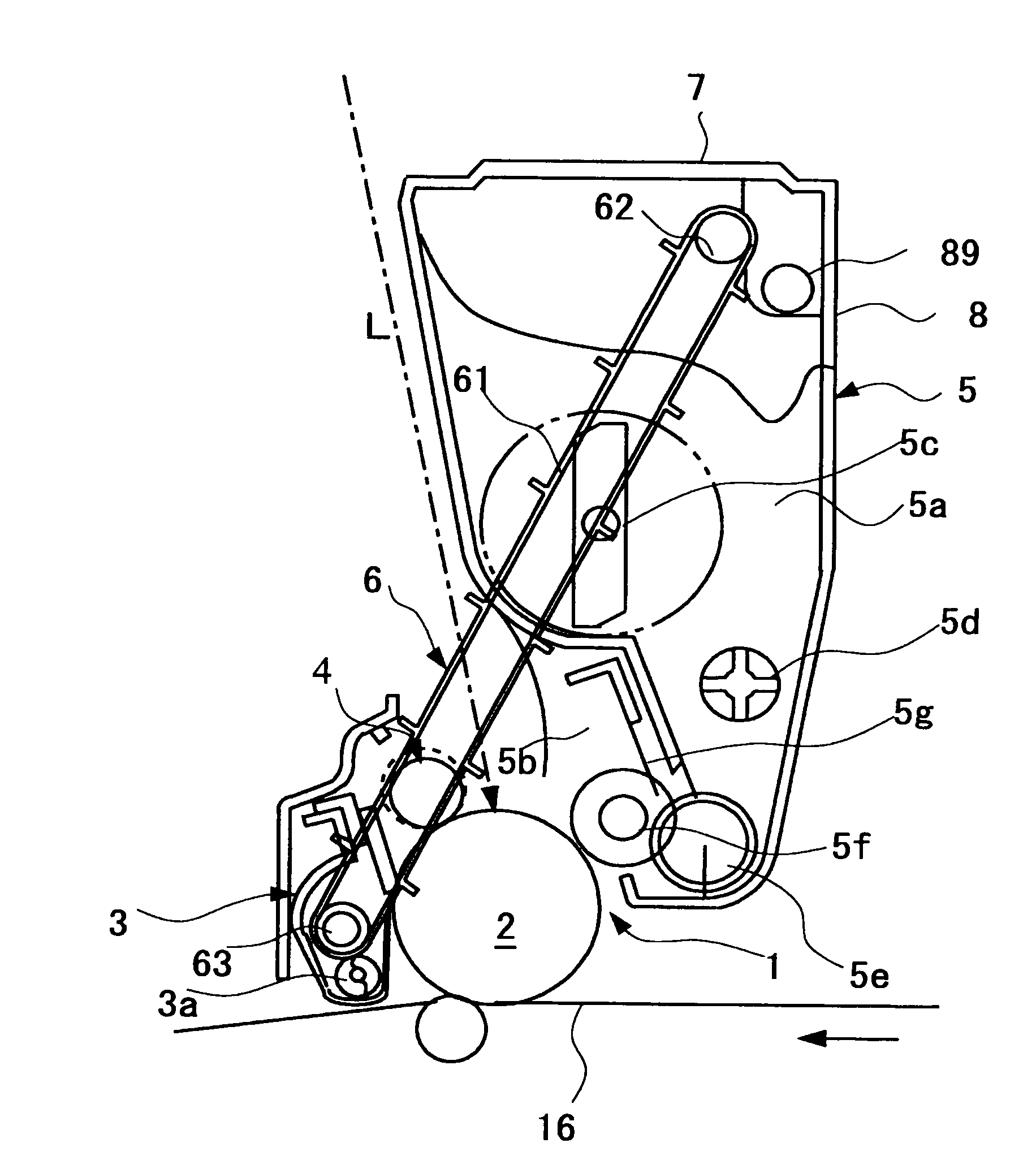
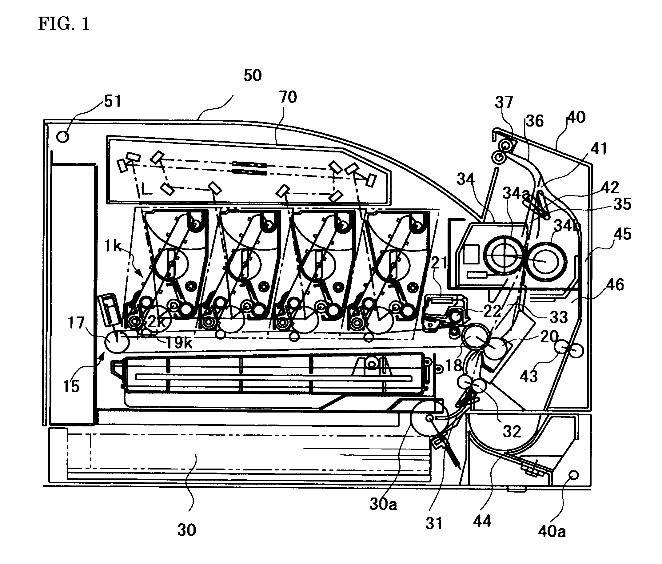
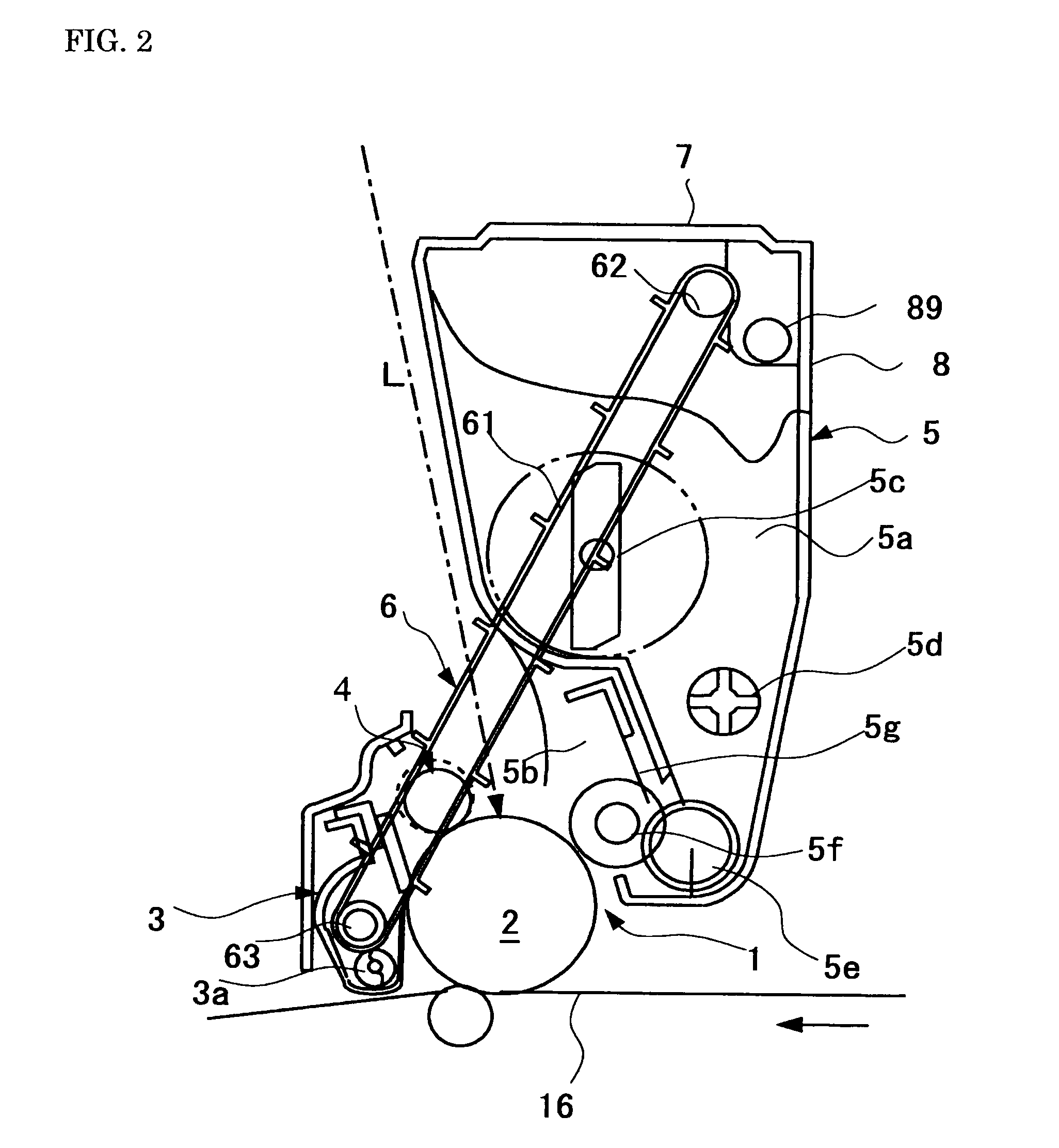
[0013]The present invention was made in view of the above described circumstances, and an object of the present invention is to solve the above described various conventional problems and to achieve the following objects. That is, an object of the present invention is to provide a toner recovery apparatus for transporting a waste toner collected by a cleaning unit to a waste toner recovery part above, wherein toner spillage is suppressed in the toner transporting duet, so as to effectively transport the toner to the recovery unit, a process cartridge, and an image forming apparatus.

Problems solved by technology

However, the current situation is that the process cartridge with a vertical structure for achieving further reduced size in the above described related art still fails to realize sufficient performance as a waste toner recovery mechanism.
While such a transportation form is suitable for a horizontal process cartridge having a transporting duct with a comparatively gentle slope, however, in the case of necessarily taking a structure where the slope of the transporting duct has to be sharp, like a vertical process cartridge, the efficiency of transporting the waste toner disclosed in JP-A No. 08-15971 is insufficient, and in the same way as described in JP-B No. 3281595, there causes a problem where the waste toner on the way of transportation duct is spilled down from a gap between the bottom of the transporting duct and convex parts on the transporting belt.

Method used


Image

  • Toner recovery apparatus, process cartridge, and image forming apparatus
  • Toner recovery apparatus, process cartridge, and image forming apparatus
  • Toner recovery apparatus, process cartridge, and image forming apparatus

Examples


examples

[0130]The present invention will be then further specifically explained in detail with reference to Examples. However, the present invention is not limited to the following Examples. In addition, all of parts indicate parts by mass in Examples.

(Preparation of Toner Particles in Pulverization Method)

[0131]

As a vinyl monomer,styrene600g,butyl acrylate110g,acrylic acid30g, anddicumyl peroxide as a polymerization initiator30gwere charged in a dropping funnel.Among monomers of polyester,polyoxypropylene(2.2)-2,2-bis(4-hydroxyphenyl)propane1,230g,(as polyol)polyoxyethylene(2.2)-2,2-bis(4-hydroxyphenyl)propane290g,(as polyol)isododecenyl succinic anhydride250g,terephthalic acid310g1,2,4-benzenetricarboxylic anhydride180g, anddibutyl tin oxide (as esterification catalyst)7g

were charged in a 5 ml four-neck flask equipped with a thermometer, a stainless stirring device, an flow type condenser and an nitrogen induction tube, while stirring in a mantle heater at a temperature of 160° C. under a...


PUM


Abstract

To provide a toner recovery apparatus including: a toner transporting duct; and an endless toner transporting belt; wherein the toner transporting belt is rotated in a loop form in such a way that it descends in a region where the outer circumferential surface faces a ceiling surface of the toner transporting duct and that it rises in a region where the outer circumferential surface of the toner transporting belt faces a bottom surface of the toner transporting duct, the toner recovery apparatus transports the residual toner to the outlet by holding the toner by the convex parts, spaces formed between convex parts and the bottom surface of the toner transporting duct, and the toner comprises a binding resin, releasing agent, coloring material and external additive, and torque T (mNm) measured by torque measurement method using a conical rotor in a space ratio of 50% to 60% is 1.0 to 2.5.

Description

BACKGROUND OF THE INVENTION[0001]1. Field of the Invention[0002]The present invention relates to a toner recovery apparatus, a process cartridge, and an image forming apparatus, which are used for the formation of an electrophotographic image in an electrostatic copier, a laser printer, and the like.[0003]2. Description of the Related Art[0004]Recent demands for compact, high-speed, and low-cost electrostatic copiers and laser beam printers have prompted the development of compact, low-cost, and high-speed printers that are designed particularly for use in a small office or home office and for individual users.[0005]Along with such a trend, full color laser printers that employ a tandem development system and an intermediate transfer method system are being predominated. Various makers have tried to downsize the integral process cartridge or the printer machine itself by devising the position or layout of the cartridge in the main body.[0006]An example of a method for downsizing a p...

Claims


Application Information

Patent Timeline
Patent Type & Authority Applications(United States)
IPC IPC(8): G03G21/10
CPCG03G21/12G03G21/105G03G2221/1624
Inventor HAGI, MASAYUKIMIKURIYA, YOSHIHIROSEKIGUCHI, YOSHITAKAYASUNAGA, HIDEAKIKATO, KIROAKIFUWA, KAZUOKIINOUE, MASAHIDESHIMIZU, YOSHIYUKI
Owner RICOH KK
Why Eureka
Try Eureka