Cutting Insert for Turning with Chip-Breaker Arrangement Providing Room for a Cooling Jet

a cutting insert and cooling jet technology, applied in the direction of cutting inserts, shaping cutters, manufacturing tools, etc., can solve the problems of difficult to come close to the cutting zone and lift the chip by means of a high-pressure jet, short service life, and high temperature of the cutting insert, so as to improve the service life, improve the machining effect, and reduce the effect of cutting for

Active Publication Date: 2008-08-21
SECO TOOLS AB
View PDF7 Cites 31 Cited by
  • Summary
  • Abstract
  • Description
  • Claims
  • Application Information

AI Technical Summary

Benefits of technology

[0002]Many of the cutting inserts found today have some form of boss near the nose-cutting edge in order to form, lead, and / or angle the chip flow. Because of said design, it is difficult to come close to the cutting zone and lift the chip by means of a high-pressure jet. This becomes especially evident at flat angles of the high-pressure jet. In order to solve this problem, use is made of entirely planar cutting plates without chip breakers, or cutting inserts without chip breakers near the nose-cutting edge and frequently in combination with very high pressures. Consequently, this brings about higher temperatures in the cutting insert and shorter service life, but also higher costs because of the expensive equipment and expensive operation. Furthermore, a planar cutting insert entails high cutting forces. A known cutting insert has recesses, preferably near the cutting edge or even breaking through the cutting edge. The latter geometry cannot be used in practice in dry machining, since the edge will be weakened.
[0004]It is desirable to provide a cutting insert having improved service life and improved machining results.
[0005]It is desirable to provide a cutting insert that gives low cutting forces.

Problems solved by technology

Because of said design, it is difficult to come close to the cutting zone and lift the chip by means of a high-pressure jet.
Consequently, this brings about higher temperatures in the cutting insert and shorter service life, but also higher costs because of the expensive equipment and expensive operation.
Furthermore, a planar cutting insert entails high cutting forces.
The latter geometry cannot be used in practice in dry machining, since the edge will be weakened.

Method used


Image

  • Cutting Insert for Turning with Chip-Breaker Arrangement Providing Room for a Cooling Jet
  • Cutting Insert for Turning with Chip-Breaker Arrangement Providing Room for a Cooling Jet
  • Cutting Insert for Turning with Chip-Breaker Arrangement Providing Room for a Cooling Jet

Examples


Embodiment Construction

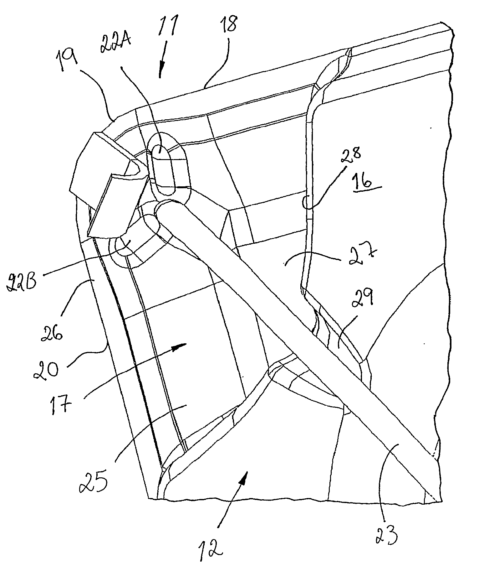
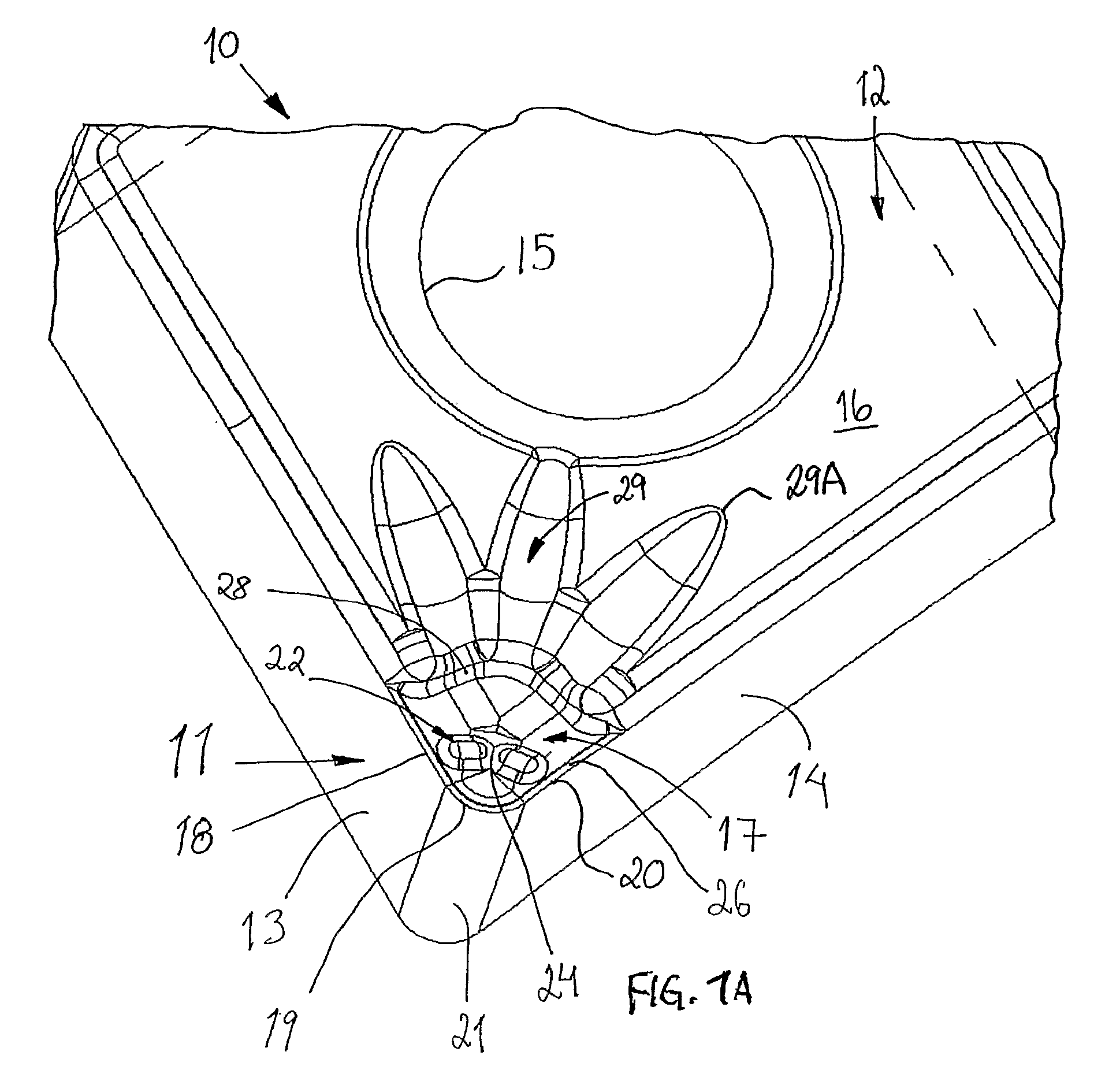
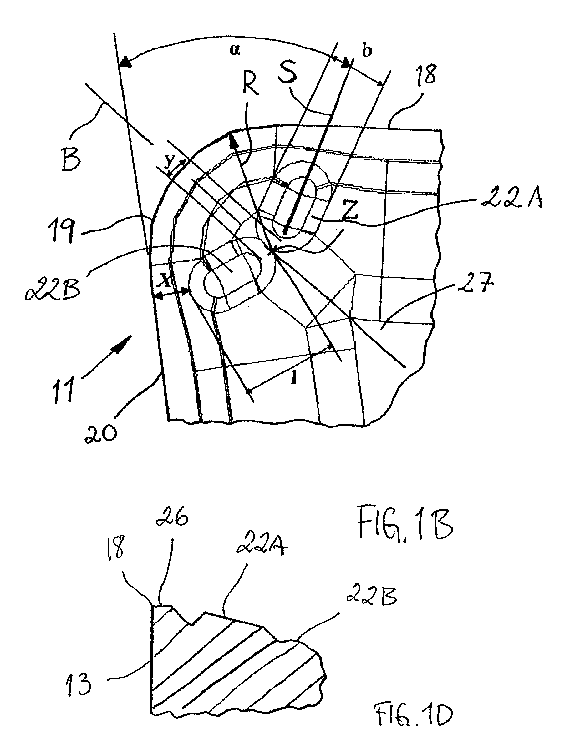
[0014]FIGS. 1A, 1B and 1C show a cutting corner 11 in an embodiment of a cutting insert 10 according to the present invention. The cutting insert 10 has a polygonal basic shape and may be double-sided. The cutting insert 10 is made from a hard, wear-resistant material, preferably cemented carbide, but may alternatively be of ceramics or cubic boron nitride (CBN). The most common hard material in cemented carbide is wolfram carbide, WC, and a binder metal. Alternative carbides may be of the metals titanium (TiC), tantalum (TaC) and niobium (NbC). The most common binder metal is cobalt (Co), but also nickel (Ni) is found. The cemented carbide is a powder mixture built up by carbide particles having grain sizes of 0.5-10 μm and a binder metal. The percentage by volume of the binder metal is 5-40% and the percentage by volume of the carbides is 95-60%. The cutting insert 10 is preferably coated with a layer of, e.g., Al2O3, TiN and / or TiCN.

[0015]The cutting insert 10 is developed to be ...


PUM

PropertyMeasurementUnit
grain sizesaaaaaaaaaa
tip angleaaaaaaaaaa
tip angleaaaaaaaaaa

Abstract

A cutting insert includes a polygonal body of a hard, wear-resistant material, which has an upper surface and a lower surface, and a plurality of edge surfaces uniting said surfaces. At least one chip-breaker arrangement is provided in at least one of the lower and upper surfaces. At least one rounded cutting corner, provided with a nose-cutting edge, is formed at a nose portion at the area of the intersection area of two edge surfaces. The cutting corner defines a bisector. The chip-breaker arrangement includes two elongate chip-breaker segments having an opening provided therebetween intended to give room for a cooling jet directed toward the opening.

Description

BACKGROUND AND SUMMARY[0001]The present invention relates to a cutting insert for turning.[0002]Many of the cutting inserts found today have some form of boss near the nose-cutting edge in order to form, lead, and / or angle the chip flow. Because of said design, it is difficult to come close to the cutting zone and lift the chip by means of a high-pressure jet. This becomes especially evident at flat angles of the high-pressure jet. In order to solve this problem, use is made of entirely planar cutting plates without chip breakers, or cutting inserts without chip breakers near the nose-cutting edge and frequently in combination with very high pressures. Consequently, this brings about higher temperatures in the cutting insert and shorter service life, but also higher costs because of the expensive equipment and expensive operation. Furthermore, a planar cutting insert entails high cutting forces. A known cutting insert has recesses, preferably near the cutting edge or even breaking t...

Claims


Application Information

Patent Timeline
Patent Type & Authority Applications(United States)
IPC IPC(8): B23B27/10B23B27/22B23C5/16B23C5/28
CPCB23B27/10B23B27/1618B23B27/1622B23B2200/0452B23B2200/086B23B2200/126Y10T407/235B23B2200/321B23B2250/12Y10T407/24Y10T407/14Y10T407/11B23B2200/245B23B27/22
Inventor JONSSON, MATSERIKSSON, THOMAS
Owner SECO TOOLS AB
Why Eureka
Try Eureka