
Automatic test equipment capable of high speed test

a test equipment and high-speed technology, applied in the direction of electrical testing, measurement devices, instruments, etc., can solve the problem of limiting the capability of ate systems, and achieve the effect of increasing the maximum operating frequency of fpga

Active Publication Date: 2008-08-28
SAMSUNG ELECTRONICS CO LTD
View PDF5 Cites 24 Cited by
  • Summary
  • Abstract
  • Description
  • Claims
  • Application Information

AI Technical Summary

Benefits of technology

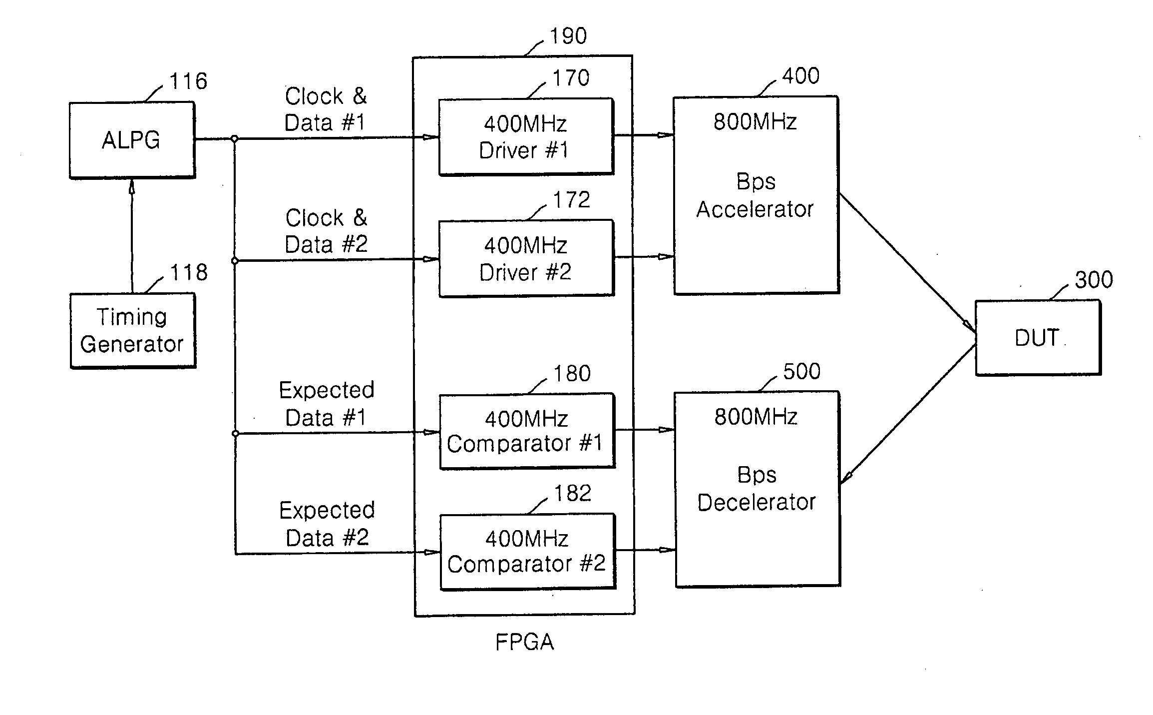
[0015]Embodiments of the present invention provide an automatic test equipment (ATE) capable of performing a high-speed test by including an accelerator and a decelerator at one end of an FPGA of the ATE body, thereby increasing the maximum operating frequency of the FPGA by at least 2 times, and performing a high-speed test of a device under test (DUT).

Problems solved by technology

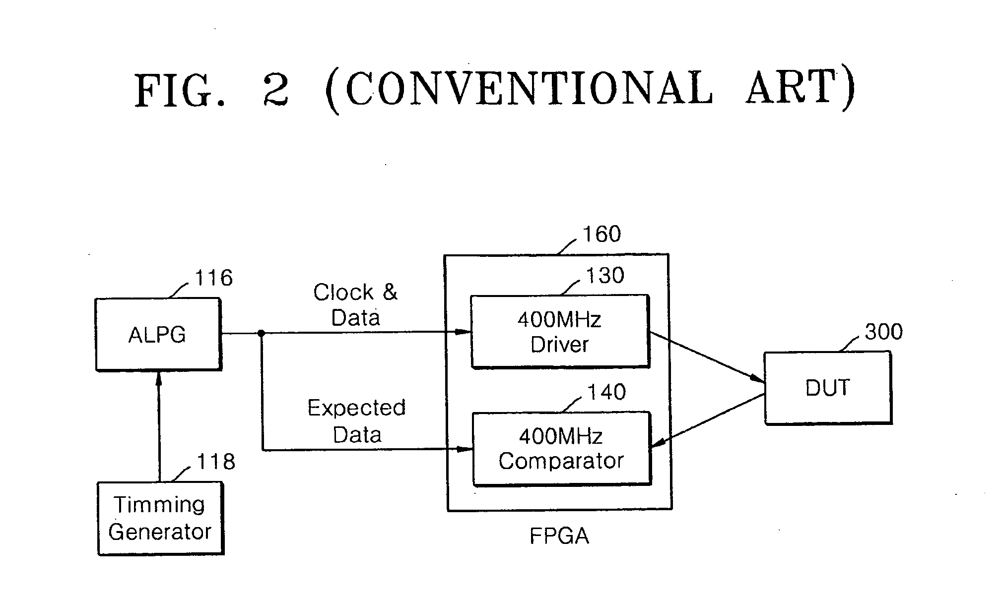
The capacitance of the semiconductor including FPGA circuits mainly prevent the maximum operating frequency of the FPGA 160 from being greater than 400 MHz in contemporary systems, which limits the capability of ATE systems.

Method used


Image

  • Automatic test equipment capable of high speed test
  • Automatic test equipment capable of high speed test
  • Automatic test equipment capable of high speed test

Examples


Embodiment Construction

[0033]Embodiments of the present invention will now be described more fully with reference to the accompanying drawings, in which exemplary embodiments of the invention are shown. The invention may, however, be embodied in many different forms, and should not be construed as being limited to the embodiments set forth herein; rather, these embodiments are provided so that this disclosure will be thorough and complete, and will fully convey the concept of the invention to those skilled in the art.

[0034]FIG. 3 is a block diagram of a system in which an accelerator and a decelerator are further configured with an FPGA capable of controlling drivers and comparators of an automatic test equipment body according to an embodiment of the present invention.

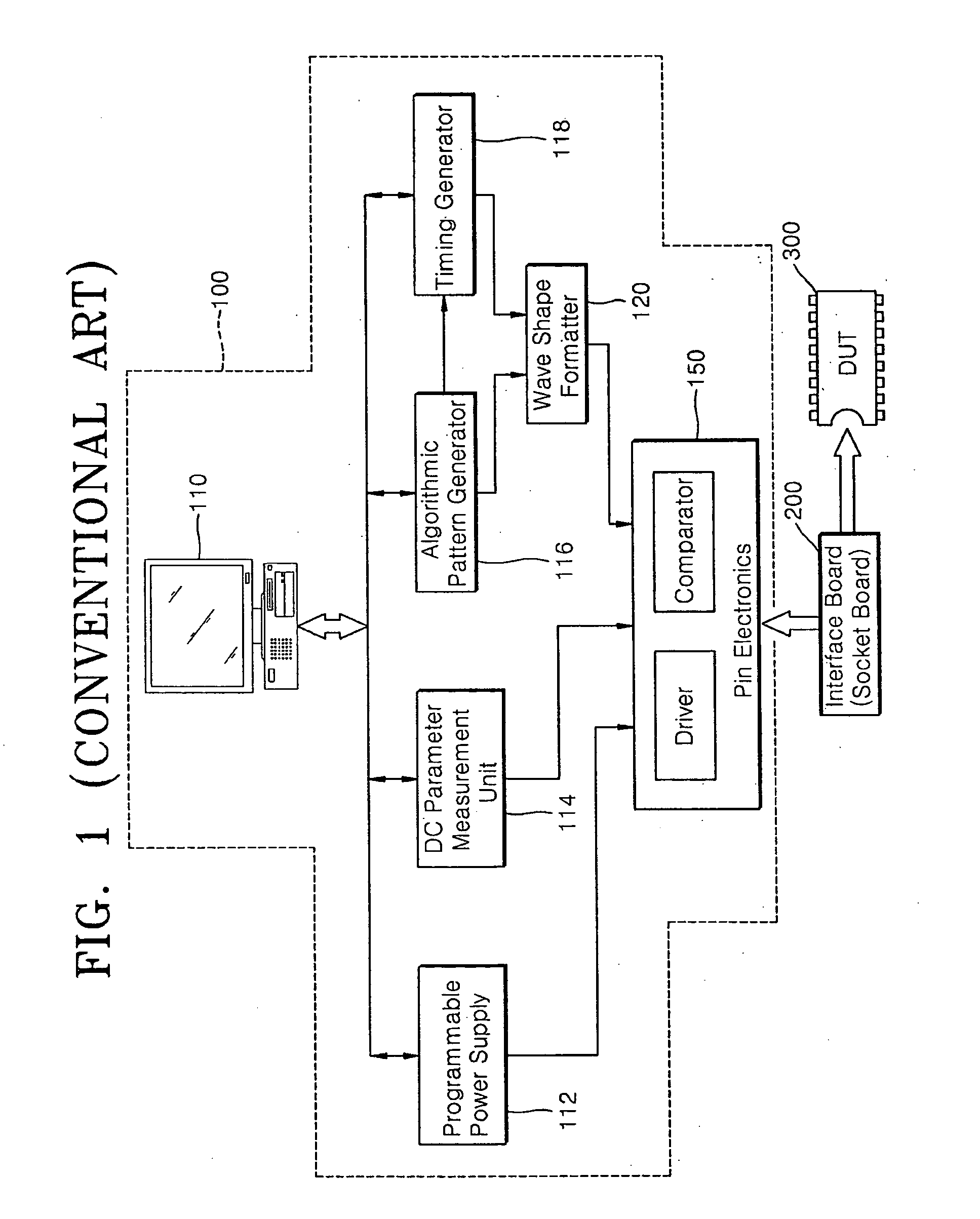
[0035]Referring to FIG. 3, an automatic test equipment (ATE) for semiconductor devices capable of performing a high-speed test according to an embodiment of the present invention includes an ATE body 100 (see FIG. 1) electrically testing se...


PUM


Abstract

Automatic test equipment is capable of performing a high-speed test of semiconductor devices, with a low cost and high efficiency. The automatic test equipment (ATE) comprises: an ATE body configured to electrically test semiconductor devices; a field programmable gate array (FPGA) controlling drivers and comparators on the ATE; an accelerator connected to an output terminal of the FPGA and that doubles an operating frequency of the FPGA; and a decelerator connected to an output terminal of the FPGA and that converts an operating frequency of data transferred from the semiconductor device to the operating frequency of the FPGA.

Description

CROSS-REFERENCE TO RELATED PATENT APPLICATION[0001]This application claims the benefit of Korean Patent Application No. 10-2007-0019919, filed on Feb. 27, 2007, in the Korean Intellectual Property Office, the disclosure of which is incorporated herein in its entirety by reference.BACKGROUND OF THE INVENTION[0002]1. Field of the Invention[0003]Embodiments of the present invention relate to the electrical testing of semiconductor devices, and more particularly, to an automatic test equipment (ATE) used for electrically testing semiconductor devices.[0004]2. Description of the Related Art[0005]Semiconductor devices are produced in a wafer state, assembled into semiconductor packages, and electrically tested, before being delivered to users. Because semiconductor memory devices such as dynamic random access memory (DRAM) have gained high capacity, high speed, and many pins, the efficiency of their electrical test processes must be increased. To increase the efficiency of the electrical ...

Claims


Application Information

Patent Timeline
Patent Type & Authority Applications(United States)
IPC IPC(8): G01R31/26
CPCG01R31/318516G01R31/31922G11C29/56012G11C29/56G01R31/31928G01R31/26G01R31/3183
Inventor JANG, CHUL-WUONGJANG, SEUNG-HOLEE, JAE-ILLEE, YOUNG-JIN
Owner SAMSUNG ELECTRONICS CO LTD
Learn More