Ejection rate measurement method, ejection rate adjustment method, liquid ejection method, method of manufacturing color filter, method of manufacturing liquid crystal display device, and method of manufacturing electro-optic device

a technology of ejection rate and measurement method, which is applied in the direction of liquid/solution decomposition chemical coating, instrumentation, superimposed coating process, etc., can solve the problems of deterioration of the measurement accuracy of ejection rate, difficulty in high-accuracy ejection rate measurement, and variation in the temperature of the droplet ejection head

Active Publication Date: 2008-08-28
KATEEVA
View PDF4 Cites 9 Cited by
  • Summary
  • Abstract
  • Description
  • Claims
  • Application Information

AI Technical Summary

Benefits of technology

[0009]The invention has an advantage of solving at least a part of the problem described above, and can be realized as following aspects or application examples.

Problems solved by technology

The variation in flow rate of the functional liquid causes a variation in amount of ejection per dot, which makes it difficult to measure the ejection rate with high accuracy.
Further, when the piezoelectric element is not driven, the piezoelectric element does not generate heat while the droplet ejection head radiates heat, which causes a variation in the temperature of the droplet ejection head.
Since the ejection rate is influenced by the temperature, a problem of deterioration of measurement accuracy of the ejection rate arises unless the ejection rate is measured in substantially the same head temperature condition at every measurement.
The droplet ejection head not sandwiched by other droplet ejection head columns has contact with air on one side, and radiates heat therefrom easily, which makes it difficult to raise the temperature.

Method used


Image

  • Ejection rate measurement method, ejection rate adjustment method, liquid ejection method, method of manufacturing color filter, method of manufacturing liquid crystal display device, and method of manufacturing electro-optic device
  • Ejection rate measurement method, ejection rate adjustment method, liquid ejection method, method of manufacturing color filter, method of manufacturing liquid crystal display device, and method of manufacturing electro-optic device
  • Ejection rate measurement method, ejection rate adjustment method, liquid ejection method, method of manufacturing color filter, method of manufacturing liquid crystal display device, and method of manufacturing electro-optic device

Examples


first embodiment

[0099]In the present embodiment, the droplet ejection device and a distinctive example of the case in which a liquid is ejected as droplets using the droplet ejection device will be explained with reference to FIGS. 1 through 9C.

[0100]Droplet Ejection Device

[0101]Firstly, the droplet ejection device 1 for coating a work by ejecting droplets will be explained with reference to FIGS. 1 through 3. Although there are used various kinds of devices as the droplet ejection device, a device using an inkjet method is preferable. The inkjet method allows ejection of microscopic droplets, and is consequently suitable for microfabrication.

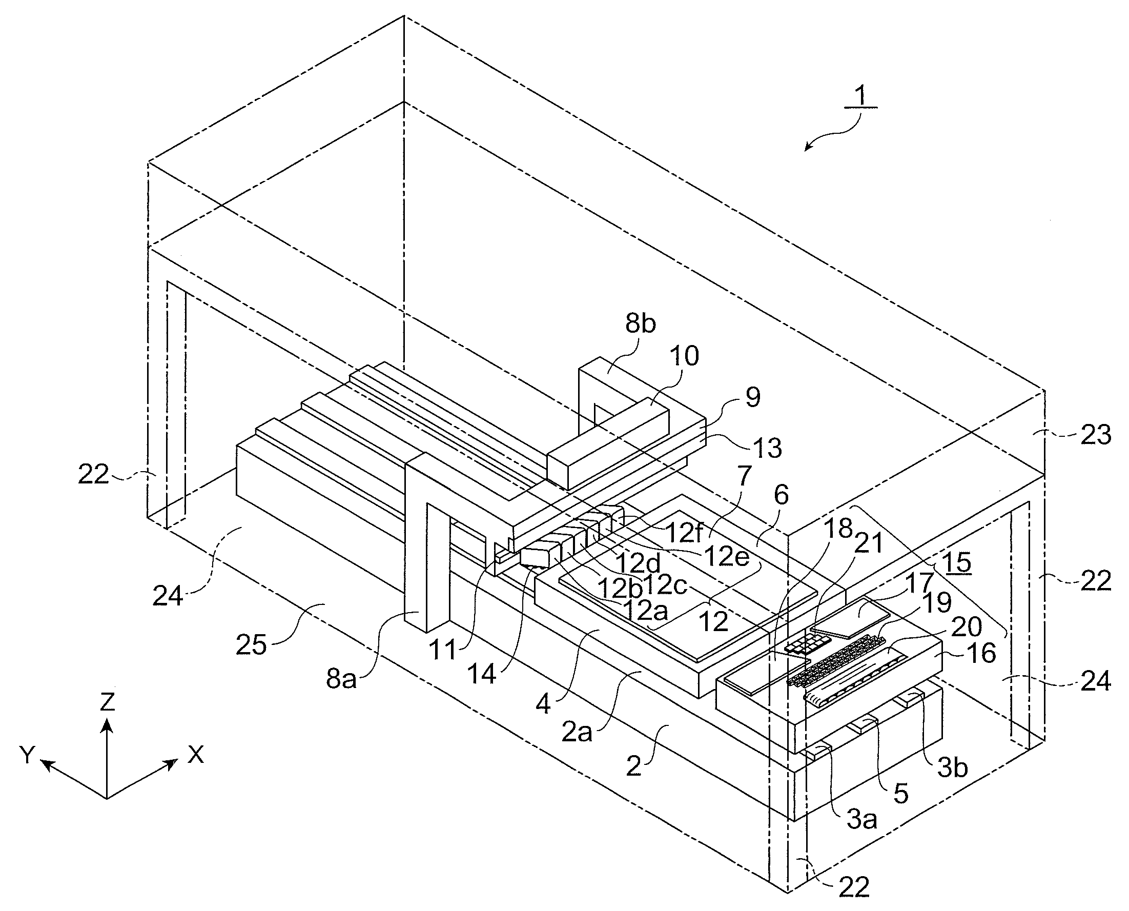
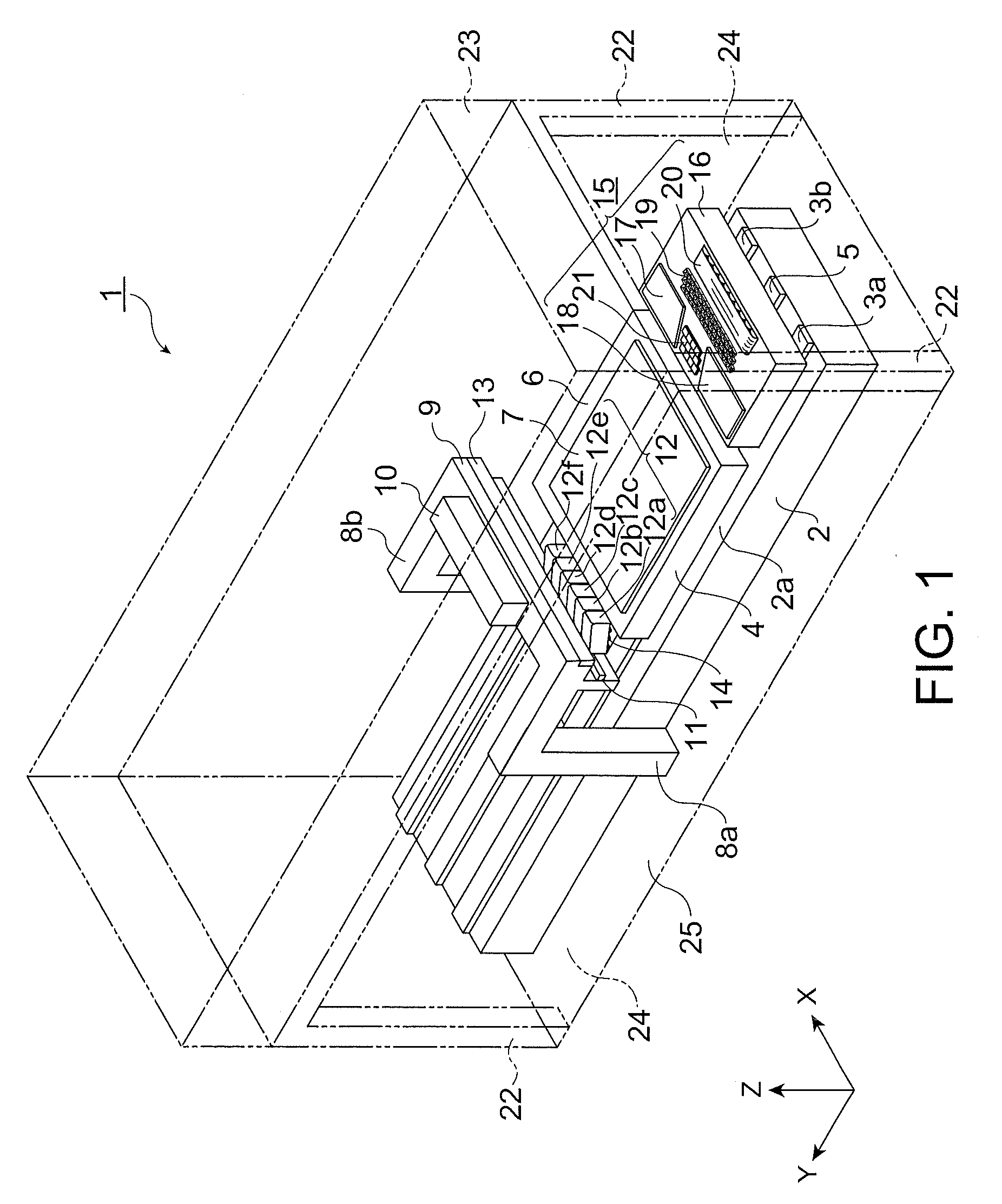
[0102]FIG. 1 is a schematic perspective view showing a configuration of the droplet ejection device. A functional liquid is ejected and applied by the droplet ejection device 1.

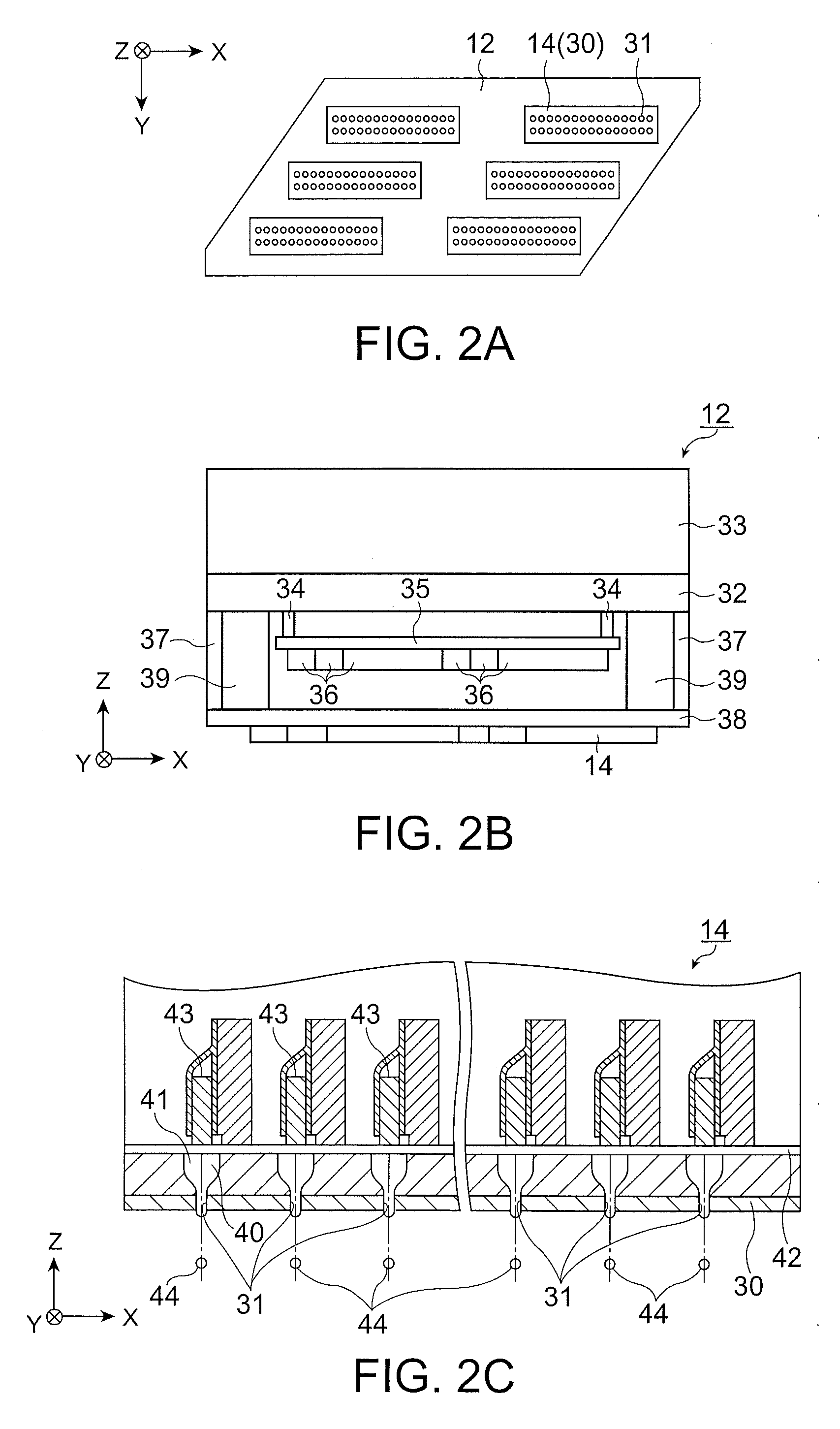
[0103]As shown in FIG. 1, the droplet ejection device 1 is provided with a platform 2 formed to have a cuboid shape. In the present embodiment, it is assumed that the longitudinal direc...

second embodiment

[0202]In the present embodiment, an embodiment of a distinctive adjustment method of adjusting the ejection rate of the droplet ejection device will be explained with reference to FIGS. 4, 5A and 5B.

[0203]The present embodiment is different from the first embodiment in that the ejection rate in all of the droplet ejection heads 14 is adjusted in the first ejection rate adjustment step.

[0204]In other words, in FIG. 4, all of the steps except the step S7 in the step S22 and the step S15 in the step S24 are the same as in the first embodiment, and therefore, the explanations therefor will be omitted. Further, in the step S7, the ejection rate of the droplet ejection heads 14 belonging to the first head column 71 through the twelfth head column 82 shown in FIGS. 5A and 5B is adjusted.

[0205]Therefore, regarding the droplet ejection heads 14 belonging to the fourth head column 74, the fifth head column 75, the eighth head column 78, and the ninth head column 79, the adjustment is performe...

third embodiment

[0210]In the present embodiment, an embodiment of a distinctive adjustment method of adjusting the ejection rate of the droplet ejection device will be explained with reference to FIG. 10. FIG. 10 is a flowchart showing a manufacturing process for coating the substrate by ejecting the droplets.

[0211]The present embodiment is different from the first embodiment in that the adjustment of the ejection rate performed in the first ejection rate adjustment step and the second ejection rate adjustment step is divided into a rough adjustment and a fine adjustment.

[0212]In FIG. 10, steps S31 through S33 are steps corresponding to the steps S1 through S3 shown in FIG. 4, and consequently, the explanations therefor will be omitted. The step S34 corresponds to an ejection measuring step, in which ejection is performed a predetermined number of times from the nozzles to the trays of the weighing device. For example, ejection is performed 100 times. After then, the weight of the trays of the weig...


PUM

PropertyMeasurementUnit
viscosityaaaaaaaaaa
temperatureaaaaaaaaaa
resistanceaaaaaaaaaa

Abstract

An ejection rate measurement method for a device having a plurality of droplet ejection head columns mounted on a plurality of carriages includes the steps of (a) measuring an ejection rate of a liquid ejected from a droplet ejection head included in one of the plurality of droplet ejection head columns sandwiched between other two of the plurality of droplet ejection head columns, (b) sandwiching, after step (a), one of the plurality of droplet ejection head columns, which has not been sandwiched between other two of the plurality of droplet ejection head columns in step (a), between other two of the plurality of droplet ejection head columns, and (c) measuring an ejection rate of a liquid ejected from a droplet ejection head included in one of the plurality of droplet ejection head columns sandwiched between other two of the plurality of droplet ejection head columns in step (b).

Description

BACKGROUND[0001]1. Technical Field[0002]The present invention relates to an ejection rate measurement method, an ejection rate adjustment method, a liquid ejection method, a method of manufacturing a color filter, a method of manufacturing a liquid crystal device, and a method of manufacturing an electro-optic device, and in particular to a method of measuring an ejection rate of a droplet ejected from a liquid ejection head with high accuracy.[0003]2. Related Art[0004]In the past, as a method of ejecting a droplet to a work there is known a method of ejecting it using an inkjet type droplet ejection device. The droplet ejection device is provided with a table for mounting a work such as a substrate and moving the work in one direction and a carriage moving above the table along a guide rail disposed in a direction perpendicular to the moving direction of the table. The carriage has an inkjet (herein after referred to as droplet ejection head) mounted thereon to eject droplets to th...

Claims


Application Information

Patent Timeline
Patent Type & Authority Applications(United States)
IPC IPC(8): B41J29/38
CPCB41J2/14209B41J2/155B41J2202/20B41J2202/19B41J2002/14459G09B5/062G09B11/10G09B19/08Y02E10/50
Inventor KOJIMA, KENJI
Owner KATEEVA
Why Eureka
Try Eureka