Surface measurement apparatus and method using depth of field

Active Publication Date: 2008-08-28
CAMBRIDGE RES & INSTR
View PDF5 Cites 8 Cited by
  • Summary
  • Abstract
  • Description
  • Claims
  • Application Information

AI Technical Summary

Benefits of technology

[0008]At the core of the invention is the recognition that best-focus algorithms can be used as a means of sample contour mapping for in-vivo imaging, to obviate or augment structured light or other complex arrangements. For example, a motorized stage can be used to move the subject up and down by known amounts while it is at least partially within the field of view of the imaging system. Images are taken with the subject in each stage position. By analyzing the sharpness of focus for individual features on the subject as the stage is moved to each position, it is possible to determine the height above the stage surface for each feature. Sharpness measures for features include the image volume of gradients or another measure of high-spatial frequency content. By interpolating between measurements of best-focus taken at successive positions, one can determine feature location to within 0.5 mm while taking images at moderate intervals such as every 1 mm of stage height motion.

Problems solved by technology
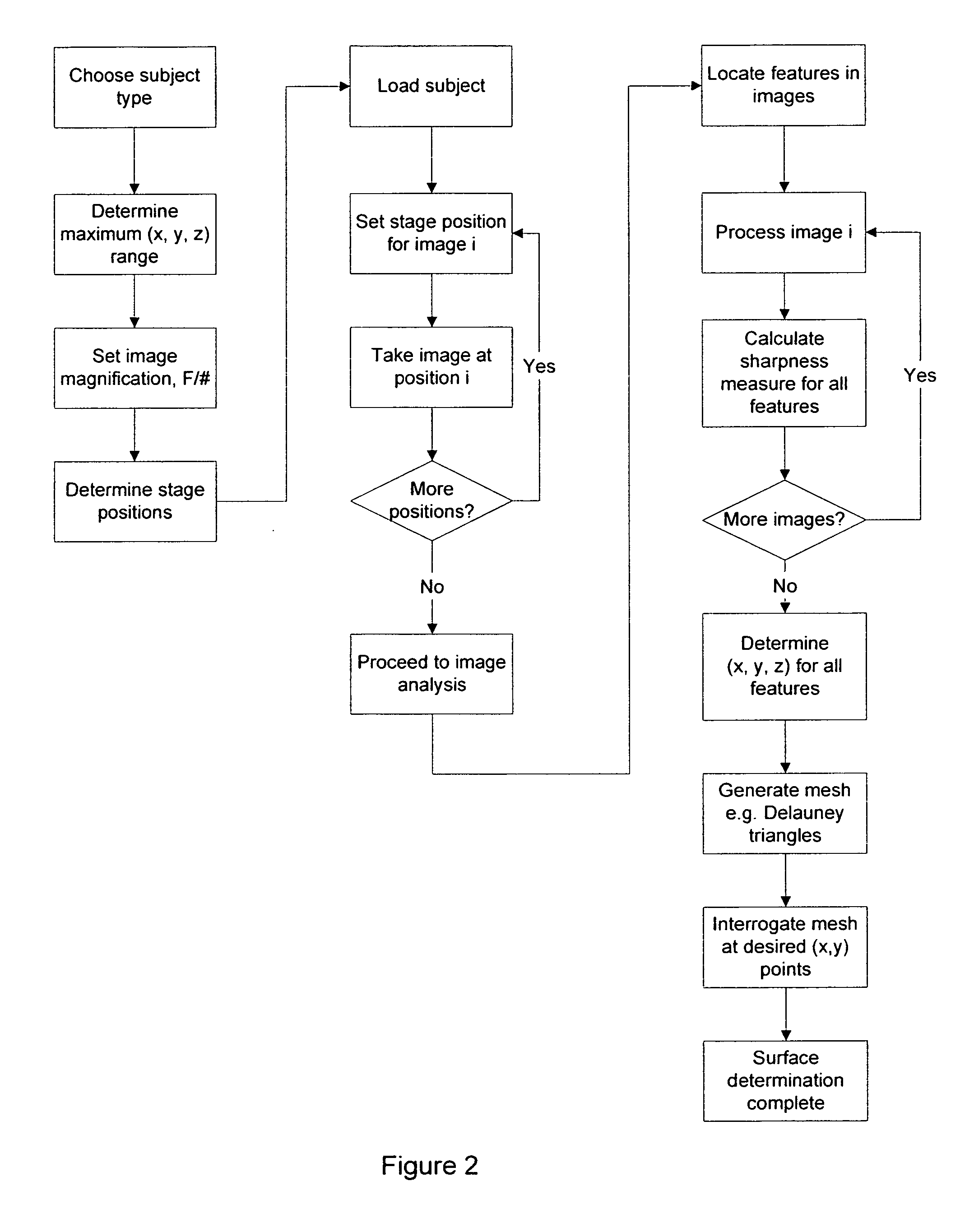
This embodiment has the disadvantage that the sub-region estimate may be weighted by the presence and location of high-contrast structures on the surface of the subject, whose location is unpredictable and possibly unknown.

Method used


Image

  • Surface measurement apparatus and method using depth of field
  • Surface measurement apparatus and method using depth of field
  • Surface measurement apparatus and method using depth of field

Examples


Embodiment Construction

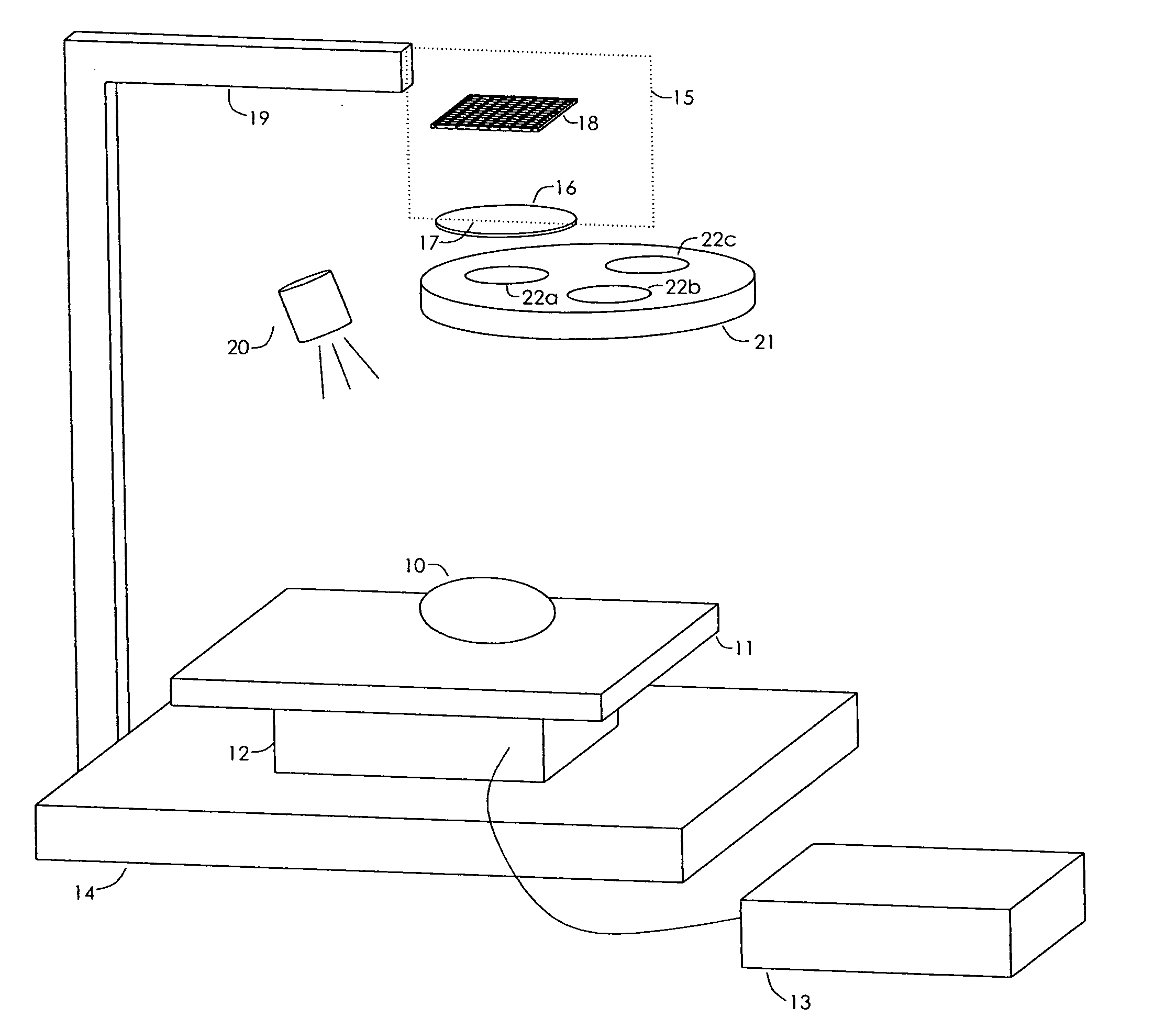
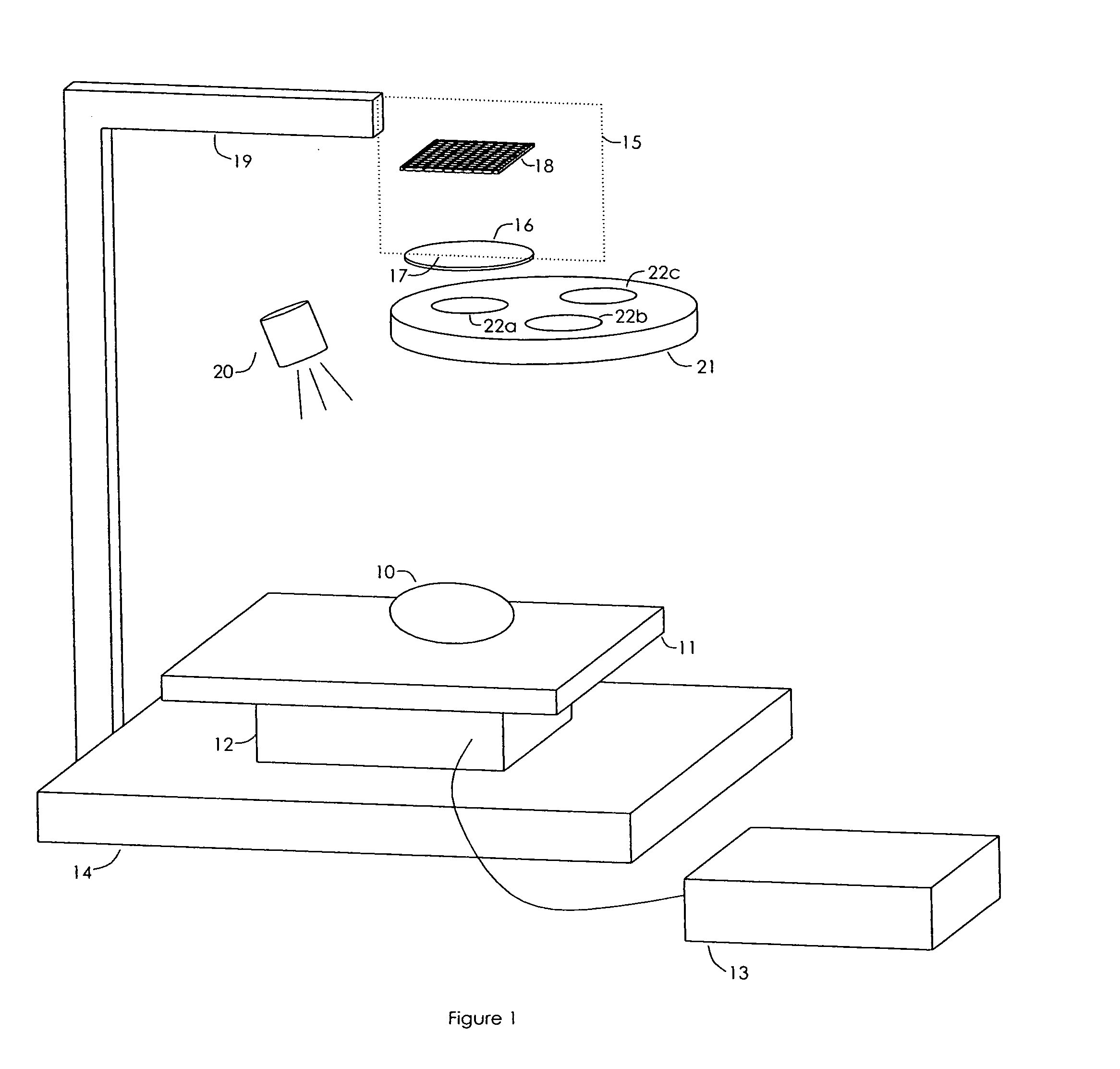
[0019]In this discussion, technical terms have their normal meanings unless stated otherwise. “Subject” refers to an intact animal subject, including without limitation a mouse, rat, human, cat, dog, monkey, zebrafish, or any other creature for which it is desired to learn its surface contours. “Object” refers to a physical object, such as a subject, whereas “image” refers to an image formed by optics of some kind.

[0020]“Lens” means a lens or lens assembly, unless a more specific term is used. “Light” means light of any type whatsoever, including ultraviolet, visible, and infrared light. “Stage” means an apparatus for holding or supporting a subject. “Height” means a specified distance above the stage. Unless stated otherwise, the coordinate system is defined where the Z axis is perpendicular to the stage surface, and the stage surface defines an X-Y coordinate plane.

[0021]The invention is best explained by relating specific embodiments. It will be understood, however, that this is ...


PUM


Abstract

The invention provides for surface mapping of in-vivo imaging subjects using a single camera and a moveable stage on which a subject animal for in-vivo imaging is placed. Images are taken and the stage is moved by known amounts along the optical axis, and the heights of individual features on the subject are determined through analysis of focus, given the known stage displacement. Alternatively, height of sub-regions of the subject are determined through analysis of focus. A mesh or other surface can be constructed from individual features, to provide a surface map of the subject. Accuracy of 0.5 mm or better can be attained for mice and similarly sized subjects.

Description

RELATED APPLICATIONS[0001]This application claims priority from U.S. Provisional Patent Application Ser. No. 60 / 877,315 which was filed on Dec. 27, 2006.BACKGROUND OF THE INVENTION[0002]In-vivo imaging systems are commercially available for imaging small animals such as mice, such as the Maestro system from CRI Inc., (Woburn Mass.), and the IVIS system from Xenogen (Hopkinton, Mass.).[0003]Motorized sample stages are widely used in optical imaging equipment, to permit loading multiple samples, or to permit selection of a sub-region of the sample for closer examination or measurement.[0004]Design of lenses and lens assemblies is discussed in a variety of textbooks such as Modern Optical Engineering, Warren J. Smith, McGraw-Hill, 3rd Edition (2000). This describes the primary aspects of a lens assembly, including entrance and exit pupils and principal plane locations, as well as the factors determining them. These may be calculated using ray-tracing programs such as Zemax from Zemax D...

Claims


Application Information

Patent Timeline
Patent Type & Authority Applications(United States)
IPC IPC(8): G01C11/12
CPCG01C11/12
Inventor DOMENICALI, PETERHOYT, CLIFFORDDETERMAN, SCOTTMILLER, PETER
Owner CAMBRIDGE RES & INSTR
Why Eureka
Try Eureka