Stent Having Controlled Porosity for Improved Ductility

a ductility and porosity technology, applied in the field of stents, can solve the problems of stents that may need to be over-expanded, vessel injury at the treatment site, and the extent of vessel restenosis, and achieve the effect of improving ductility

Inactive Publication Date: 2008-08-28
MEDTRONIC VASCULAR INC
View PDF28 Cites 29 Cited by
  • Summary
  • Abstract
  • Description
  • Claims
  • Application Information

AI Technical Summary

Benefits of technology

[0008]Embodiments of the present invention include an endoluminal prosthesis for placement in a body lumen of a metallic material having controlled porosity for improved ductility. The metallic material may be formed into a stent structure or a wire or sheet, which may then be formed into the stent structure. The porous network of the stent includes pores that range from nanometer scale to micron scale. The controlled porosity accommodates volume changes as well as provides a barrier to crack propagation to allow alloy steels and amorphous metal materials, which would otherwise be considered too brittle for the demands of intraventional use, to be utilized in a stent.

Problems solved by technology

In certain instances due to the stretching of the vessel wall that occurs during a PTCA procedure, the stretching and widening of the vessel to reopen the lumen and the subsequent making of the vessel patent for facilitating revascularization of the heart tissue can result in vessel injury at the treatment site.
The resulting trauma to the vessel wall contributes to the extent and occurrence of restenosis of the vessel.
A problem associated with stent expansion at the treatment site is that the stent may need to be over expanded in order to compensate for high metallurgical recoil, which occurs in many stents made of high strength materials, such as, stainless steel, MP35N, ELGILOY, nitinol, L605, magnesium, niobium, and tantalum.
This over expansion can contribute to the trauma that occurs to the vessel wall.
However, these requirements are often competing and / or contradictory, such that a sacrifice or trade-off between one or more properties is customarily required in choosing a stent material.

Method used


Image

  • Stent Having Controlled Porosity for Improved Ductility
  • Stent Having Controlled Porosity for Improved Ductility

Examples


Embodiment Construction

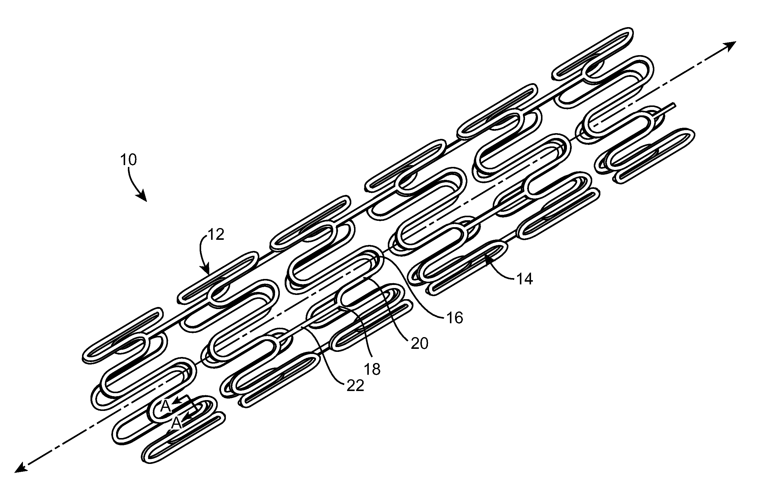
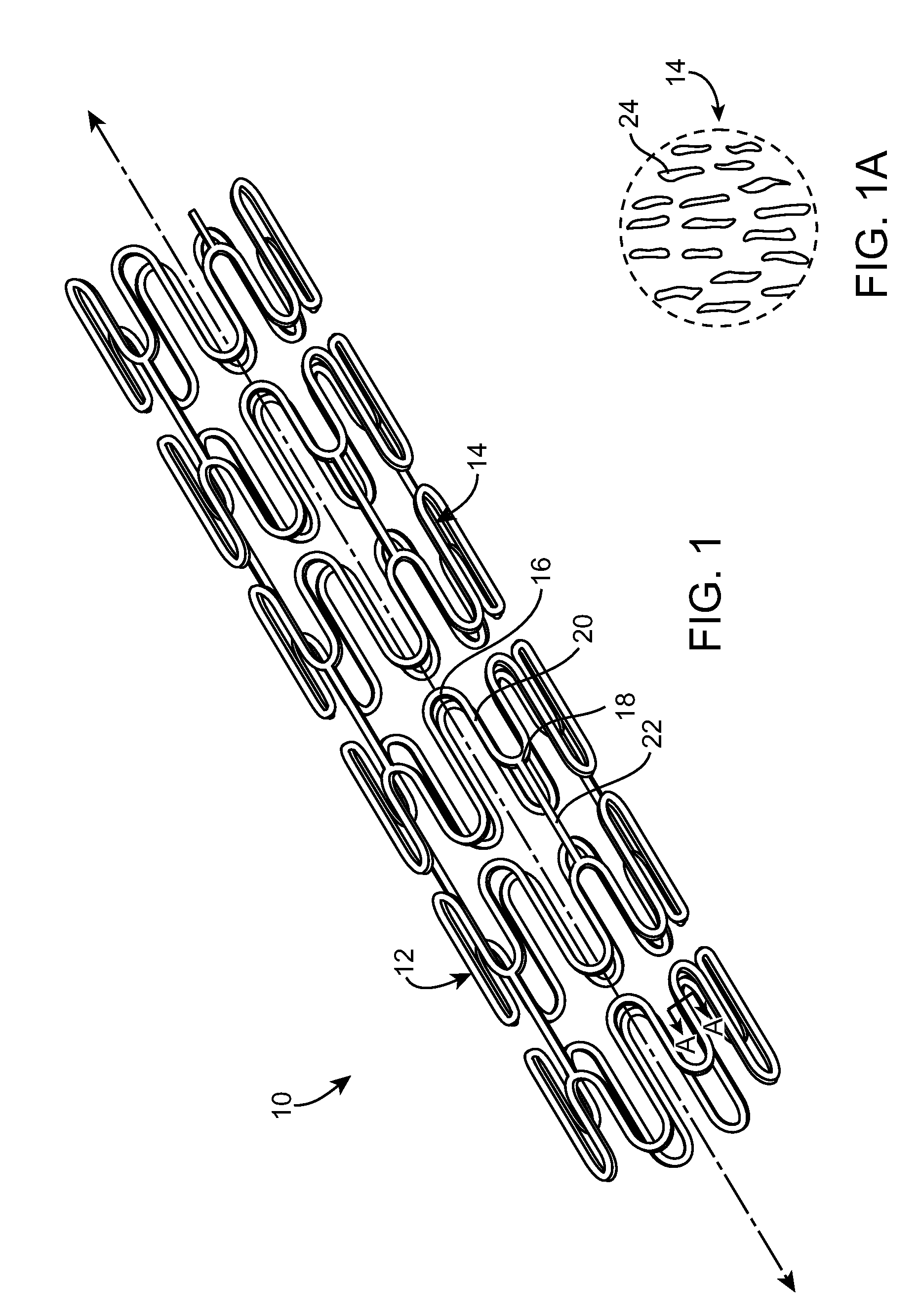
[0012]The following detailed description is merely exemplary in nature and is not intended to limit the invention or the application and uses of the invention. Although the description of embodiments of the invention may be in the context of treatment of blood vessels, the invention may also be used in any other body passageways where it is deemed useful. Furthermore, there is no intention to be bound by any expressed or implied theory presented in the preceding technical field, background, brief summary or the following detailed description.

[0013]Many high strength materials, such as alloy steels and amorphous metals, exhibit poor ductility that limits there ability to be used in vascular stent applications. In accordance with embodiments of the present invention, in order to improve ductility, these materials may be formed into a wire, sheet or tube having a 3-D porous network with pores that range from nanometer scale to micron scale. The pores allow volume changes as well as pro...


PUM

PropertyMeasurementUnit
pore sizeaaaaaaaaaa
thicknessesaaaaaaaaaa

Abstract

An endoluminal prosthesis for placement in a body lumen of a metallic material having controlled porosity for improved ductility. The metallic material may be formed into a stent structure or a wire or sheet, which may then be formed into the stent structure. The porous network of the stent includes pores that range from nanometer scale to micron scale. The controlled porosity accommodates volume changes as well as provides a barrier to crack propagation to allow alloy steels and amorphous metal materials, which would otherwise be considered too brittle for the demands of intraventional use, to be utilized in a stent.

Description

FIELD OF THE INVENTION[0001]The invention relates generally to endoluminal prostheses for placement in a body lumen, and more particularly to stents made of a metallic material having a controlled porosity that provides ductility for improved performance.BACKGROUND OF THE INVENTION[0002]A wide range of medical treatments exist that utilize “endoluminal prostheses.” As used herein, endoluminal prostheses is intended to cover medical devices that are adapted for temporary or permanent implantation within a body lumen, including both naturally occurring and artificially made lumens, such as without limitation: arteries, whether located within the coronary, mesentery, peripheral, or cerebral vasculature; veins; gastrointestinal tract; biliary tract; urethra; trachea; hepatic shunts; and fallopian tubes.[0003]Accordingly, a wide assortment of endoluminal prostheses have been developed, each providing a uniquely beneficial structure to modify the mechanics of the targeted lumen wall. For ...

Claims


Application Information

Patent Timeline
Patent Type & Authority Applications(United States)
IPC IPC(8): A61F2/86
CPCA61F2/91A61F2/915A61F2002/91558A61F2230/0013A61L31/022A61L31/146A61F2250/0023
Inventor KRIVORUCHKO, MICHAELALLEN, JEFFREYBIRDSALL, MATTHEW J.
Owner MEDTRONIC VASCULAR INC
Why Eureka
Try Eureka