Control Method of Direct Injection Engine, Controller for Implementing the Control method, and Control Circuit Device Used for the Controller

a technology of direct injection and control method, which is applied in the direction of electric control, combustion air/fuel air treatment, instruments, etc., can solve problems such as taking into account the relationship between, and achieve the effects of improving the power of a direct injection internal combustion engine, improving volumetric efficiency, and increasing engine power

Inactive Publication Date: 2008-08-28
HITACHI LTD
View PDF4 Cites 28 Cited by
  • Summary
  • Abstract
  • Description
  • Claims
  • Application Information

AI Technical Summary

Benefits of technology

[0007]With a direct injection engine, gas in the cylinder is cooled by the evaporation latent heat of fuel resulting in improved volumetric efficiency and higher engine power. That is, since the direct injection engine aims at improving engine power by use of fuel evaporation, the fuel injection control according to fuel evaporation characteristics is necessary to obtain higher engine power.
[0008]Then, an object of the present invention is to provide a fuel injection control technique which makes it possible to maximize engine power according to fuel evaporation characteristics.
[0012]In accordance with the thus-configured present invention, gas in the cylinder is appropriately cooled by the evaporation latent heat of fuel resulting in improved volumetric efficiency and higher engine power, making it possible to improve the power of a direct injection internal combustion engine.

Problems solved by technology

However, the above-mentioned conventional technique describes a technique for performing fuel injection control according to fuel evaporation characteristics to achieve exhaust gas reduction but does not take into consideration the relationship between the fuel injection control for exhaust gas reduction and the improvement of engine power.

Method used


Image

  • Control Method of Direct Injection Engine, Controller for Implementing the Control method, and Control Circuit Device Used for the Controller
  • Control Method of Direct Injection Engine, Controller for Implementing the Control method, and Control Circuit Device Used for the Controller
  • Control Method of Direct Injection Engine, Controller for Implementing the Control method, and Control Circuit Device Used for the Controller

Examples


first embodiment

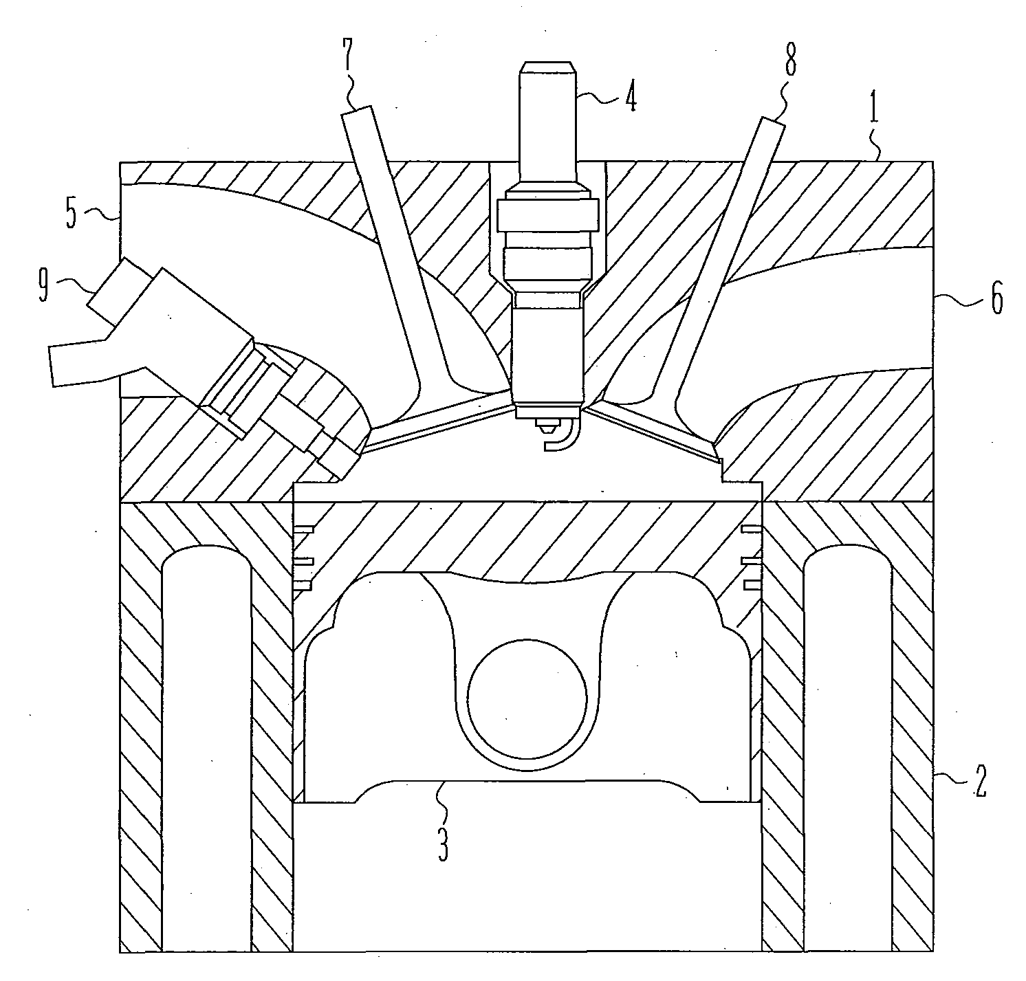
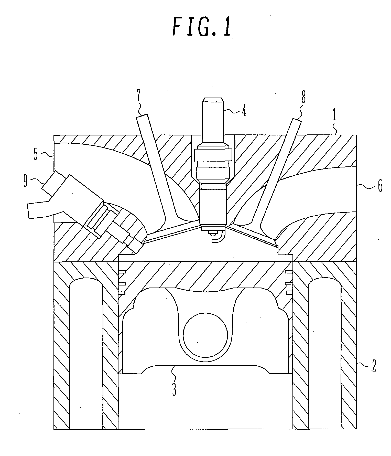
[0059]Configurations of a direct injection engine according to a first embodiment are shown in FIGS. 1 and 2. FIG. 1 is a central sectional view of a direct injection engine according to the present embodiment, and FIG. 2 is a perspective view of the direct injection engine according to the present embodiment.

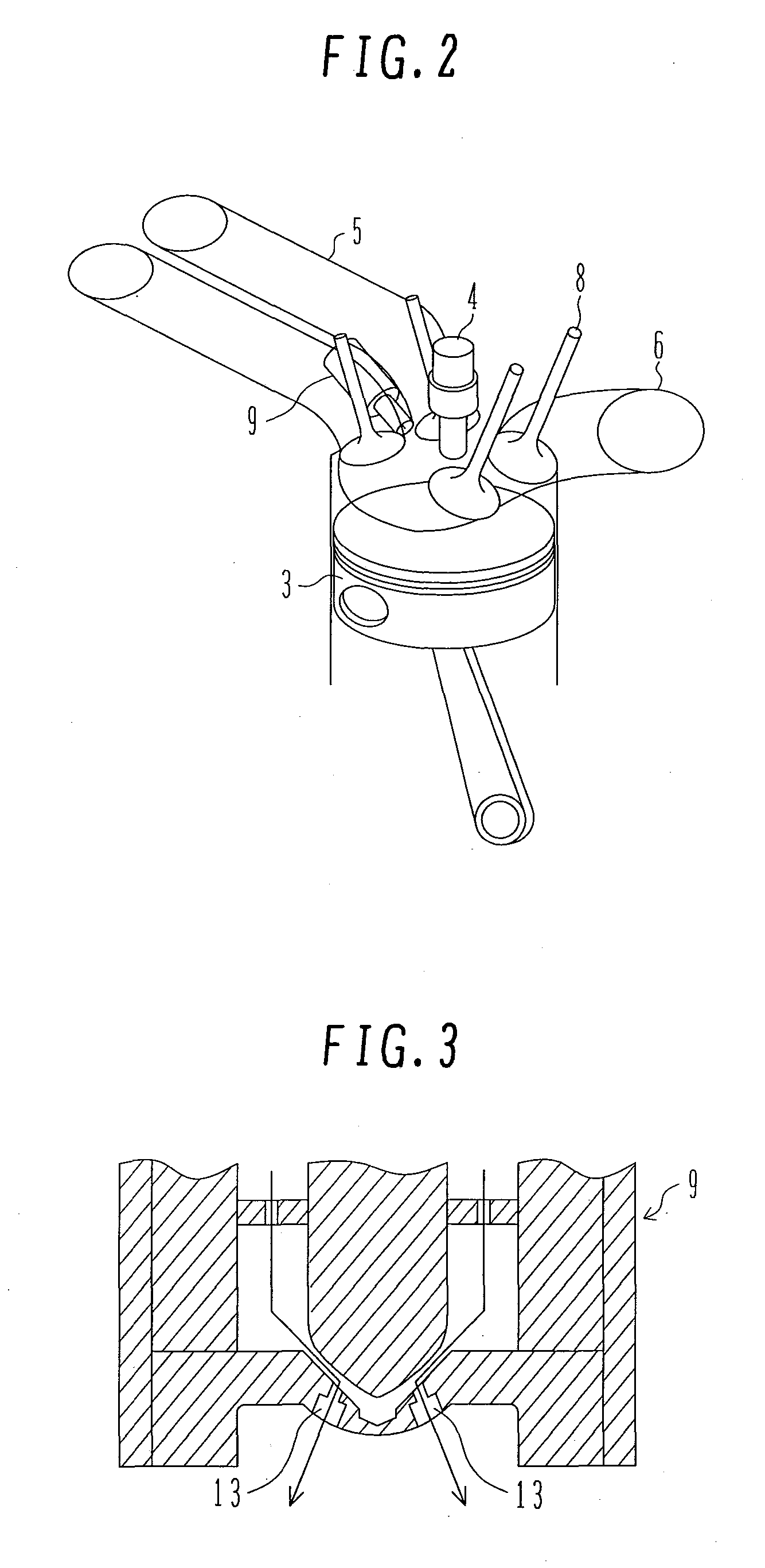
[0060]A combustion chamber is formed by a cylinder head 1, a cylinder block 2, and a piston 3 inserted in the cylinder block 2; an ignition plug 4 is provided at the top center of the combustion chamber. A intake pipe 5 and an exhaust pipe 6 open into the combustion chamber, which are provided with a intake valve 7 and an exhaust valve 8, respectively, to open and close each opening. An injector 9 is provided on the intake side of the combustion chamber so as to inject fuel directly into the combustion chamber.

[0061]The injector 9 used in the first embodiment injects fuel pressurized to about 10 to 20 MPa at a high speed from microscopic pores provided at the end of the nozzle ...

second embodiment

[0101]Then, an embodiment using mixed gasoline will be explained below.

[0102]Ethanol-blended gasoline is known as a mixed fuel. Since each saturated vapor pressure differs between ethanol and gasoline, the saturated vapor pressure of the mixed fuel depends on the concentration of mixed ethanol as shown in FIG. 28. Generally, the saturated vapor pressure of the mixed fuel increases with increasing ethanol concentration. This means that the fuel evaporation time increases with increasing ratio of mixed ethanol. Then, as shown in the FIG. 29, the engine power can be improved by detecting a concentration of ethanol contained in the fuel and delaying the fuel injection timing in the intake stroke injection mode with increasing ethanol concentration. In connection with detection of the ethanol concentration, disclosures, for example, in JP-A-2006-77683 can be utilized. The calorific value per unit mass of ethanol is smaller than that of gasoline. Therefore, in order to obtain the same cal...


PUM


Abstract

An object of the present invention is to provide a fuel injection control technique which maximizes engine power according to fuel evaporation characteristics. The fuel injection timing in the intake stroke is delayed according as a physical quantity affecting the fuel evaporation time changes such that the fuel evaporation time decreases. Further, the fuel injection timing when a physical quantity affecting the fuel evaporation time is such that the fuel evaporation time decreases is set closer to the end of the intake stroke than the fuel injection timing when the physical quantity is such that the fuel evaporation time increases. The fuel injection timing is controlled so as to maximize engine power according to fuel evaporation times.

Description

BACKGROUND OF THE INVENTION[0001]1. Field of the Invention[0002]The present invention relates to a control method of an engine with direct fuel injection into the cylinder (so-called a direct injection engine) and more particularly to a control method of an injector which injects fuel into the cylinder. The invention is also related to a controller for implementing the control method or a control circuit device used for the controller.[0003]2. Description of the Related Art[0004]When an engine is started up in a cold state, a catalyst provided in an exhaust gas passage cannot be activated sufficiently because of the low temperature thereof. Accordingly, unburnt gas is discharged from the engine as it is, which will significantly affect the environment.[0005]To reduce the amount of unburnt hydrocarbon (HC) discharged immediately after a cold start of an engine, it is conventionally proposed that fuel injection is performed at a later stage of the compression stroke and ignition perfo...

Claims


Application Information

Patent Timeline
Patent Type & Authority Applications(United States)
IPC IPC(8): F02D41/34F02D9/02F02M51/00F02M69/30F02M35/104
CPCF02D41/047F02D41/061F02D41/401F02D2041/0015Y02T10/44F02D2200/0414F02D2200/0606F02D2200/0611Y02T10/146F02D2041/389Y02T10/12Y02T10/40
Inventor SUKEGAWA, YOSHIHIROFUJII, HIROSHI
Owner HITACHI LTD
Why Eureka
Try Eureka