Method for programming phase-change memory and method for reading date from the same

Inactive Publication Date: 2008-09-04
LONGITUDE SEMICON S A R L
View PDF4 Cites 24 Cited by
  • Summary
  • Abstract
  • Description
  • Claims
  • Application Information

AI Technical Summary

Benefits of technology

[0024]It is an object of the present invention to provide a novel program

Problems solved by technology

Thus, even if it is supposed that a resetting speed of 10 ns or less and a setting speed of 30 ns or less could be realized in a phase-change memory, set programming cannot be effected in pulse signals of one shot, and the above-described operating speed cannot be achieved.
For example, programming may be carried out only in continuous determined page units, but adopting such a configuration not only prevents the high-speed and random access as in an ordina

Method used


Image

  • Method for programming phase-change memory and method for reading date from the same
  • Method for programming phase-change memory and method for reading date from the same
  • Method for programming phase-change memory and method for reading date from the same

Examples


first exemplary embodiment

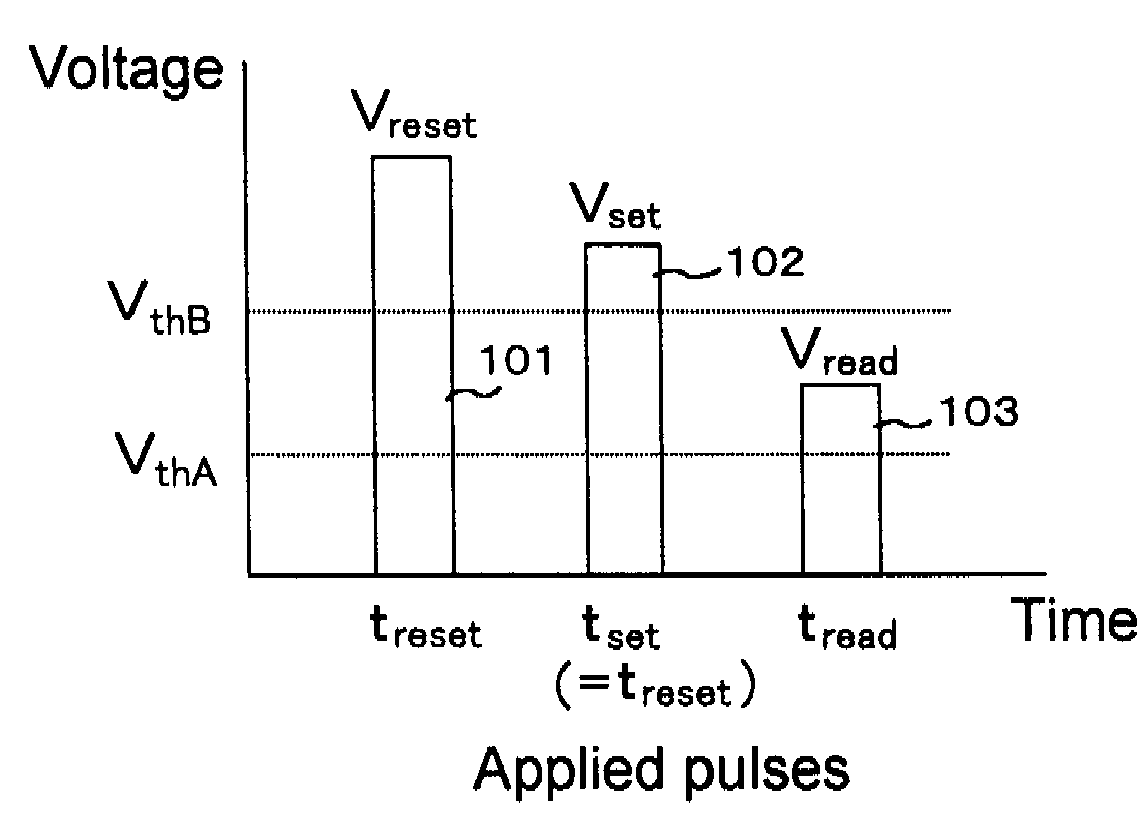
[0046]FIG. 4 shows the voltage waveform of programming pulses and a read pulse based on the method of programming a phase-change memory according to the first exemplary embodiment. As described in the foregoing explanation, there are two types of programming pulses; a resetting pulse used for placing a phase-change element that is in the crystalline state into the amorphous state, and a setting pulse used for placing the phase-change element that is in the amorphous state into the crystalline state. A read pulse is not a pulse for changing the phase state of the phase-change element but rather a pulse applied to the phase-change element for reading the phase state of the phase-change element.

[0047]In the first exemplary embodiment, resetting pulse 101 is a pulse having voltage Vreset for supplying the current necessary for placing a phase-change element that is in the crystalline state into the amorphous state, and has a pulse width treset necessary for making the change to the amor...

second exemplary embodiment

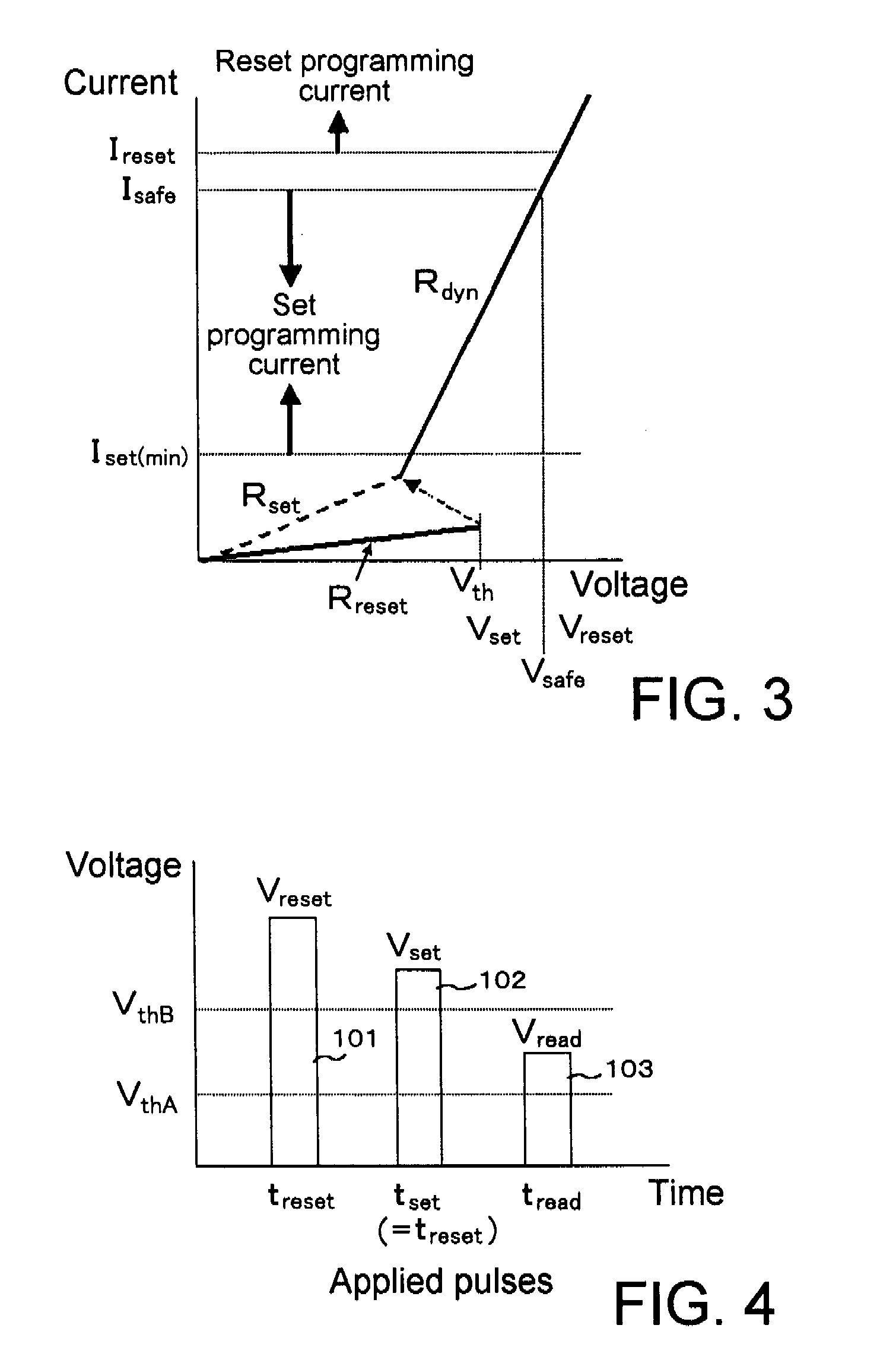
[0068]Explanation next regards the second exemplary embodiment of the present invention. FIG. 9 shows the current-voltage characteristic for a case in which dynamic resistance Rdyn is set to approximately twice the value used in the phase-change memory of the first exemplary embodiment. Dynamic resistance Rdyn can be made high resistance by selecting the material making up the heater Making the dynamic resistance higher improves the efficiency of heat generation. Put more simply, doubling dynamic resistance Rdyn causes doubling of R in the expression (I2R) that represents the amount of generated heat, whereby the efficiency of heat generation also doubles. As a result, when the resistance value of the phase-change element is programmed to the same value, the reset and set currents in the second exemplary embodiment can be decreased to Ireset1 and Iset1, respectively, which are lower values than in the first exemplary embodiment. This reduction of current is obviously preferable from...


PUM


Abstract

When a phase-change element that can transition between a reset state (amorphous state) and a set state (crystalline state) is to be caused to transition to the reset state, a first pulse having a first voltage is applied to the phase-change element. The first voltage is higher than the threshold voltage in the reset state, and can cause current to flow that corresponds to an amount of generated heat required for placing the element in the reset state. When the phase-change element is to be caused to transition to the set state, a second pulse having a second voltage and the same time width as the first pulse is applied to the phase-change element. The second voltage that is higher than the threshold voltage but lower than the first voltage, and can cause only a current to flow that does not attain the necessary amount of generated heat.

Description

[0001]This application is based upon and claims the benefit of priority from Japanese patent application No. 2007-052787, filed on Mar. 2, 2007, the disclosure of which is incorporated herein in its entirety by reference.BACKGROUND OF THE INVENTION [0002]1. Field of the Invention[0003]The present invention relates to a programming method for recording data in a phase-change memory, and to a reading method for reading data stored in a phase-change memory.[0004]2. Description of the Related Art[0005]Similar to a memory device used in desktop equipment, high performance and high functionality are increasingly demanded of a memory device used for mobile applications, i.e., used for such purposes as portable apparatuses such as portable telephones and various other handheld information devices. A Memory device used for mobile applications must of course have high capacity on the level of, for example, a general-purpose DRAM (Dynamic Random Access Memory), must have a data bit width as la...

Claims


Application Information

Patent Timeline
IPC IPC(8): G11C7/00
CPCG11C13/0004G11C13/004G11C2213/79G11C2013/009G11C2013/0092G11C13/0069
Inventor FUJI, YUKIO
Owner LONGITUDE SEMICON S A R L
Why Eureka
Try Eureka