Optical information recording device, optical information recording method, and optical information recording medium

a recording device and optical information technology, applied in the direction of recording strategies, instruments, optical beam sources, etc., can solve the problems of inability to control the writing power, the recording characteristic may be degraded, and the recording in an optical disk may be stopped, so as to achieve the effect of easy formation of the longest record mark

Inactive Publication Date: 2008-09-04
TAIYO YUDEN KK
View PDF6 Cites 6 Cited by
  • Summary
  • Abstract
  • Description
  • Claims
  • Application Information

AI Technical Summary

Benefits of technology

[0018]According to the third technological means, for information recording, the power of blue-purple laser light is controlled using the writing power Pw, space formation power Ps, and bias power Pb. An asymmetry value indicates a difference between an amplitude center of a reproduced signal derived from the shortest record mark and shortest space and an amplitude center thereof derived from the longest record mark and longest space. As long as the bias power Pw is made higher than the read power Pr, when the writing power Pw is changed from one level to another, even if the writing power Pw is low, the longest record mark can be readily formed. Consequently, along with a change in the writing power Pw, the amplitude derived from the longest space does not vary but the amplitude derived from the longest record mark varies. Accordingly, the amplitude center derived from the longest record mark and longest space changes from one level to another, and the asymmetry value exhibits a linear functional monotonous change along with the change in the writing power Pw. Even when a disturbance occurs during information recording, an appropriate recording characteristic can be provided by changing the writing power Pw from one level to another.

Problems solved by technology

Consequently, the writing power cannot be controlled based on the asymmetry value or β value of the RF signal.
This poses a problem in that the recording characteristic may be degraded, recording in an optical disk may be ceased, or recorded information cannot be reproduced.

Method used


Image

  • Optical information recording device, optical information recording method, and optical information recording medium
  • Optical information recording device, optical information recording method, and optical information recording medium
  • Optical information recording device, optical information recording method, and optical information recording medium

Examples


first embodiment

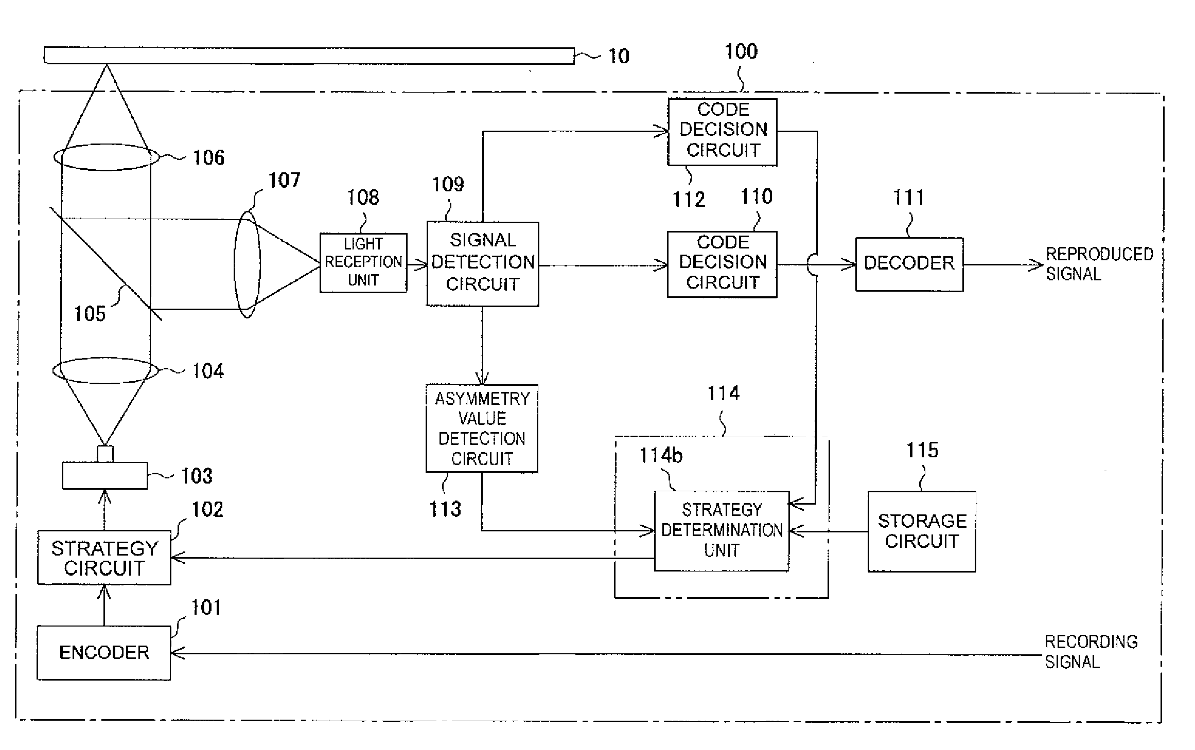
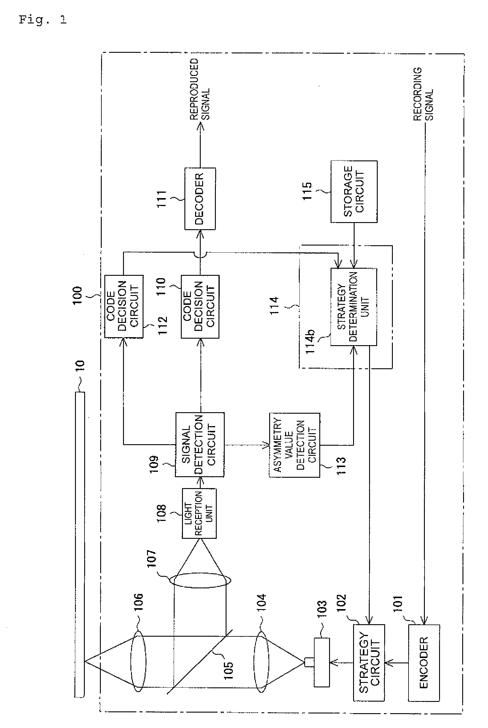
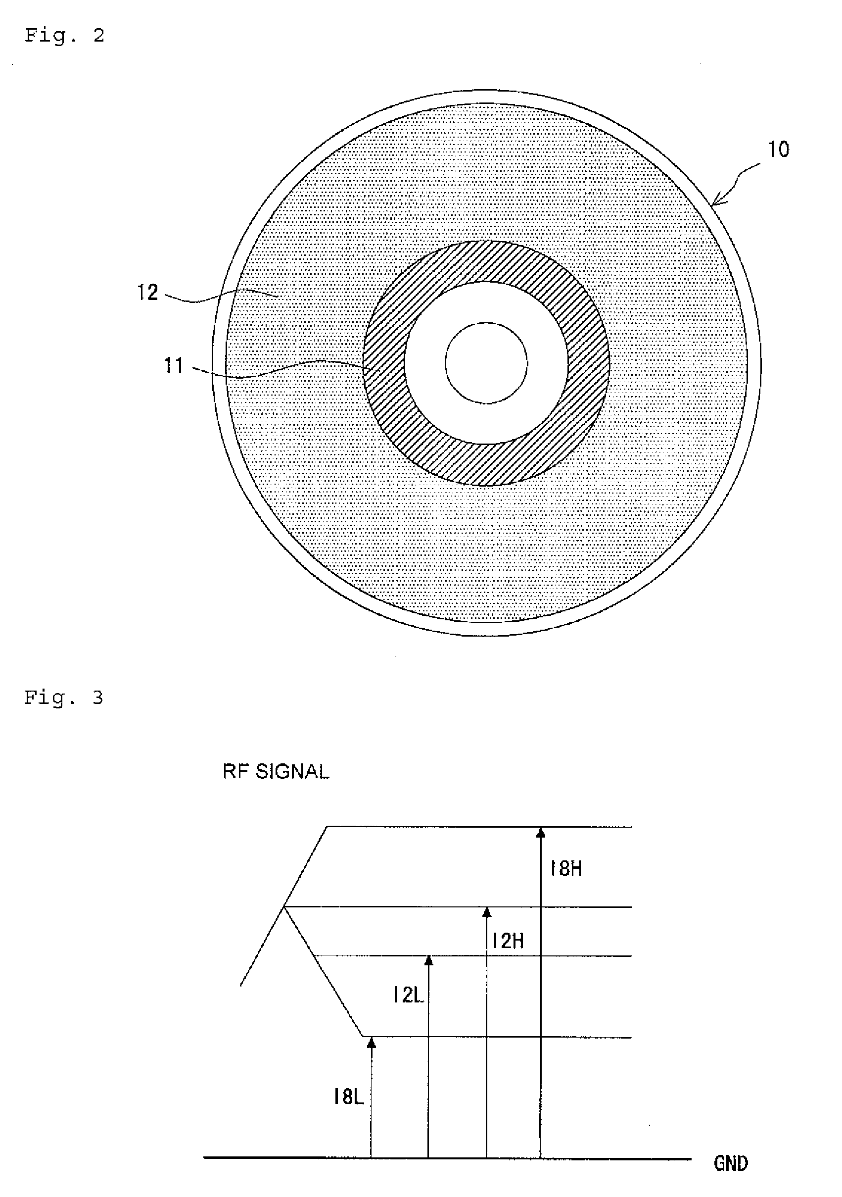
[0040]FIG. 1 to FIG. 12 show the present invention. FIG. 1 is a schematic block diagram of an optical information recording device. FIG. 2 is a plan view for use in explaining an optical disk shown in FIG. 1. FIG. 3 is a conceptual diagram showing the amplitude of a reproduced signal derived from the shortest record mark and shortest space, and the amplitude thereof derived from the longest record mark and longest space. FIG. 4 is a conceptual diagram for use in explaining recording pulses produced by a strategy circuit shown in FIG. 1. FIG. 5 is a conceptual diagram for use in explaining recording pulses needed to form the shortest record mark. FIG. 6 is a conceptual diagram for use in explaining recording pulses needed to form the second shortest record mark that ranks next to the shortest record mark. FIG. 7 is a flowchart describing writing strategy designation processing. FIG. 8 is a conceptual diagram for use in explaining a change in the amplitude center of a reproduced signa...

second embodiment

[0082]Next, referring to FIG. 16 to FIG. 18, the present invention will be described below.

[0083]FIG. 16 is a graph expressing the relationship between bias power and writing power. FIG. 17 is a schematic block diagram of an optical information recording device. FIG. 18 is a flowchart describing writing strategy designation processing.

[0084]A difference of the second embodiment from the first embodiment is that the bias power Pb, changes from one level to another as a linear function of the writing power Pw. The same reference numerals are assigned to components identical to those of the first embodiment. An iterative description will be omitted.

[0085]Specifically, the bias power Pb for the recording pulses 20 produced by the strategy circuit 102 is expressed by an equation (3) below as a linear function of the writing power Pw using a coefficient s and a constant t.

Pb=s×Pw+t  (3)

[0086]As shown in FIG. 16, the coefficient s and constant t are designated so that the bias power Pb wil...


PUM

PropertyMeasurementUnit
wavelengthaaaaaaaaaa
bias poweraaaaaaaaaa
wavelengthaaaaaaaaaa

Abstract

Provided are an optical information recording device, an optical information recording method, and an optical information recording medium which provide an appropriate recording characteristic even when a disturbance occurs during information recording. A drive forms record marks and spaces by irradiating blue-purple laser light to an optical disk, for which an organic dye exhibiting a predetermined absorption factor with respect to light having a wavelength of at or near 405 nm is used, and thus records information. For recording of information, the power of the blue-purple laser light is controlled using writing power used for forming record marks, space formation power used for forming spaces that may be higher than read power used for reproducing information recorded in an optical information recording medium, and bias power higher than read power.

Description

BACKGROUND OF THE INVENTION[0001]1. Field of the Invention[0002]The present invention relates to an optical information recording device, an optical information recording method, and an optical information recording medium that permit recording of information in an optical information recording medium for high-density recording and reproduction (hereinafter, simply, an optical information recording medium) which is writable using a laser called a blue-purple laser or a blue laser.[0003]2. Description of the Related Art[0004]Optical disks for high-density recording and reproduction including a write-once type Blu-ray disk (BD-R) or a write-once type HD-DVD disk (HD-DVD-R) have a structure that a recording layer, a reflective layer, and, if necessary, a protective layer are formed on one side of an optical-transparency disk substrate. Moreover, spiral or concentric grooves each of which is called simply a groove are formed in the side of the substrate in which the recording layer and ...

Claims


Application Information

Patent Timeline
Patent Type & Authority Applications(United States)
IPC IPC(8): G11B7/0037
CPCG11B7/00455G11B7/246G11B7/00736G11B7/00456G11B7/125G11B7/1263
Inventor MIYAZAWA, FUYUKISEKIGUCHI, MITSUOOYAMA, KATSUHIROKAKIMOTO, HIROYA
Owner TAIYO YUDEN KK
Why Eureka
Try Eureka